Amplifier circuit

A chopper amplifier and circuit technology, used in amplifiers, differential amplifiers, DC-coupled DC amplifiers, etc., can solve problems such as large peak components, and achieve the purpose of reducing harmonic distortion, suppressing peak components, and eliminating the influence of slew rate. Effect

Inactive Publication Date: 2008-01-09
SII SEMICONDUCTOR CORP +1
View PDF0 Cites 17 Cited by
  • Summary
  • Abstract
  • Description
  • Claims
  • Application Information

AI Technical Summary

Problems solved by technology

Thus, a large peak component is generated in the signal

Method used


Image

  • Amplifier circuit
  • Amplifier circuit
  • Amplifier circuit

Examples


Embodiment Construction

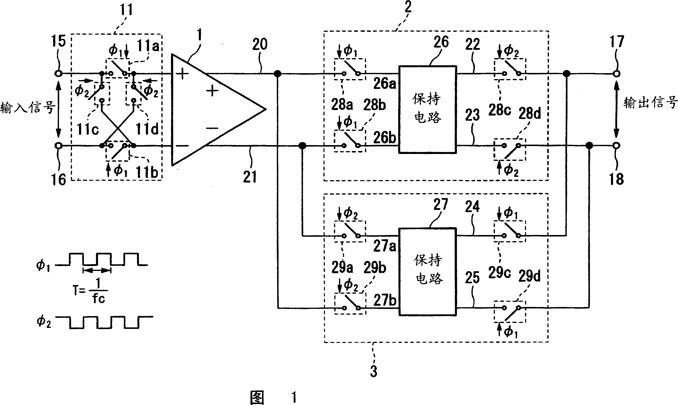
[0052] Next, a chopper amplifier circuit according to an embodiment of the present invention will be described with reference to the drawings. The block diagram shown in FIG. 1 shows a configuration example of a chopper amplifier circuit according to this embodiment.

[0053] In this drawing, the same components as those in the conventional example of FIG. 9A are denoted by the same reference numerals, and their descriptions are omitted. That is, the chopper circuit 11 and the amplifier 1 are the same as those in the conventional example of FIG. 9A. The circuit of FIG. 1 differs from the conventional example in that it includes sample-and-hold circuits 2 and 3 connected in parallel in the subsequent stage of the amplifier 1 instead of the chopper circuit 12 in the conventional example.

[0054] The circuit of this embodiment works the same as the conventional example, so a brief description is made for the structure of the chopping circuit 11

[0055] The chopper circuit 11 ...


PUM


Abstract

Provided is a chopper amplifier circuit capable of eliminating an influence of a slew rate of an amplifier and suppressing spike generation to thereby obtain an output signal having little harmonic distortion. The chopper amplifier circuit according to the present invention includes: a first chopper circuit for chopping an input signal by a first pulse and a second pulse shifted from each other in phase by a half cycle, switching a relation of connection between an input terminal pair and an output terminal pair at a timing of the chopping, and outputting the input signal as a modulated signal; an amplifier for amplifying the modulated signal and outputting the modulated signal thus amplified as an amplified signal; a first sample hold circuit for holding the amplified signal at the first pulse and outputting the amplified signal at the second pulse; and a second sample hold circuit for holding the amplified signal at the second pulse and outputting the amplified signal at the first pulse.

Description

technical field [0001] The present invention relates to chopper amplifier circuits capable of reducing DC offset and noise in amplifiers, and more particularly, to chopper amplifier circuits capable of reducing the effects of spike noise. Background technique [0002] Chopper amplifier circuits are widely used as low noise, low drift DC amplifiers. [0003] As shown in FIG. 9A , a conventional chopper amplifier includes an amplifier 1, and chopper circuits 11 and 12 provided at the preceding and subsequent stages of the amplifier 1, respectively, so as to realize low-noise amplification. [0004] The chopper circuit 11 employs four switching devices that are turned on and off according to the pulses [phi]1 and [phi]2 shown in FIG. 9B. Pulses 1 and 2 are phase-shifted rectangular pulses. The switching device is periodically controlled based on the pulses [phi]1 and [phi]2 to determine which of the input signals input to the input terminals 15 and 16 is to be input to the ...

Claims


Application Information

Patent Timeline
Patent Type & Authority Applications(China)
IPC IPC(8): H03F3/45H03F1/08
CPCH03F2203/45614H03F2203/45212H03F3/45986H03F2203/45681H03F2203/45726H03F2203/45138H03F3/45995H03F2203/45616H03F3/45475H03F1/3211H03F3/387H03F1/26
Inventor 吉泽浩和安斋亮一内田俊之武田晃有山稔五十岚敦史
Owner SII SEMICONDUCTOR CORP
Why Eureka
Try Eureka