Eureka AIR delivers breakthrough ideas for toughest innovation challenges, trusted by R&D personnel around the world.

Touching control panel

A touch panel and control terminal technology, applied in the direction of instruments, electrical digital data processing, electrical components, etc., can solve the problem of not knowing whether the pixel Pa has been touched, reducing user convenience, and the photosensitive element PD cannot feel Light source current and other issues

Active Publication Date: 2008-01-09
AU OPTRONICS CORP
View PDF0 Cites 46 Cited by
  • Summary
  • Abstract
  • Description
  • Claims
  • Application Information

AI Technical Summary

Problems solved by technology

[0003] However, the disadvantage of the pixel Pa of the touch panel in the prior art is that when there is no light source in the surrounding environment (such as placing the touch panel in a dark place), the photosensitive element PD cannot sense the light source and generate Therefore, it is impossible to know whether the pixel Pa has been touched. As a result, the application range of the touch panel made of the pixel Pa will be limited, and the convenience of the user will be greatly reduced.

Method used

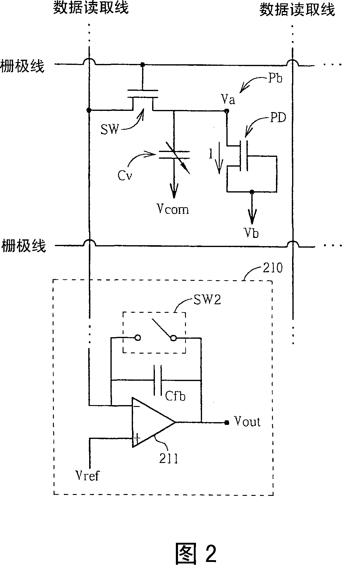
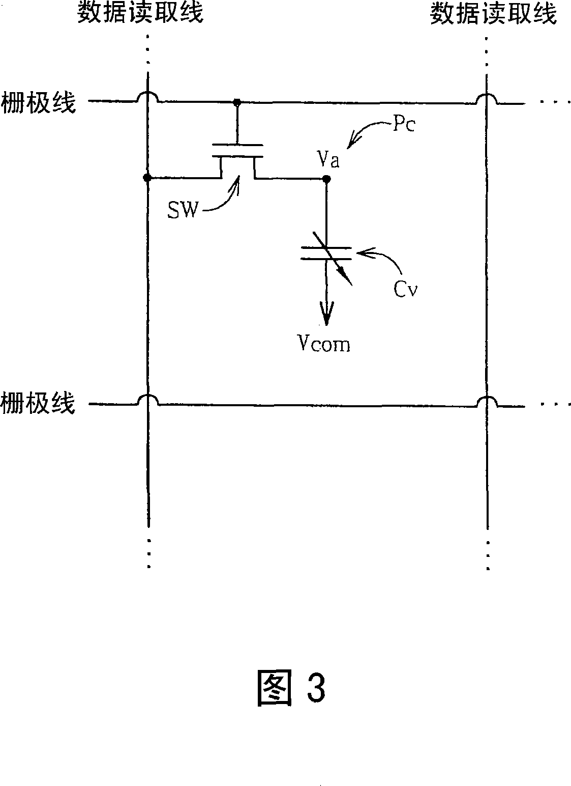

Image

  • Touching control panel
  • Touching control panel
  • Touching control panel

Examples


Embodiment Construction

[0032] Please refer to Figure 2. FIG. 2 is a schematic diagram of a pixel Pb of the touch panel of the present invention. As shown in the figure, the pixel Pb is similar to the pixel Pa, and the same parts will not be repeated here. The difference is that the pixel Pb adds a variable capacitor Cv to the second terminal of the switch SW. One terminal of the variable capacitor Cv is coupled to the second terminal of the switch SW, and the other terminal is coupled to a common terminal Vcom (that is, the common terminal carries a voltage Vcom). And when the pixel Pb is touched, the capacitance value of the variable capacitor Cv will change, thus also affecting the magnitude of the potential Va. In this way, when the pixel Pb is not touched, the photosensitive element PD will generate a current I to affect the potential Va; when the pixel is touched, the photosensitive element PD will not generate a current I but the capacitance value of the variable capacitor Cv will also change...


PUM


Abstract

The touch control type faceplate includes multiple pixels. Each pixel includes a sensitization element, a pressure-sensing element, and a switch. When sensing, the sensitization element generates first sense signal. When being pressed, the pressure-sensing element generates second sense signal. The switch includes following parts: a first end connected to the sensitization element and the pressure-sensing element; a control end in use for receiving a signal driven by a grid; and a second end in use for transferring the first sense signal and the second sense signal based on the said signal driven by the grid. Thuds, in the invention, even if there is no light source on surrounding environment, pixels can determine whether the touch control type faceplate is set a finger on based on capacitance magnitude of variable capacity.

Description

technical field [0001] The present invention relates to a touch panel, in particular to a touch panel with pixels of photosensitive elements and pressure sensitive elements. Background technique [0002] Please refer to Figure 1. FIG. 1 is a schematic diagram of a pixel Pa of a touch panel in the prior art. As shown in the figure, the pixel Pa includes a switch SW and a photosensitive element PD. The switch SW can be a thin film transistor (Thin Film Transistor, TFT); the photosensitive element PD can be a photodiode. One end of the photosensitive element PD is coupled to the second end of the switch SW, and the other end is coupled to a bias voltage source Vb. When the photosensitive element PD receives a light source (indicating that it is not touched), it will generate a current I, and pull down the potential Va to Vb; conversely, when the photosensitive element PD does not receive a light source (indicating that it has been touched), it will not A current I is genera...

Claims


Application Information

Patent Timeline
Patent Type & Authority Applications(China)
IPC IPC(8): G06F3/042H03K17/96H03K17/78
Inventor 李信宏刘柏源江明峰刘俊欣陈纪文
Owner AU OPTRONICS CORP
Why Eureka
Eureka Blog
Learn More