Axial force controlling nut assembly
An axial force, nut technology, applied in the direction of threaded fasteners, screws, connecting components, etc., can solve problems such as difficulties
- Summary
- Abstract
- Description
- Claims
- Application Information
AI Technical Summary
Problems solved by technology
Method used
Image

Examples
Embodiment 1
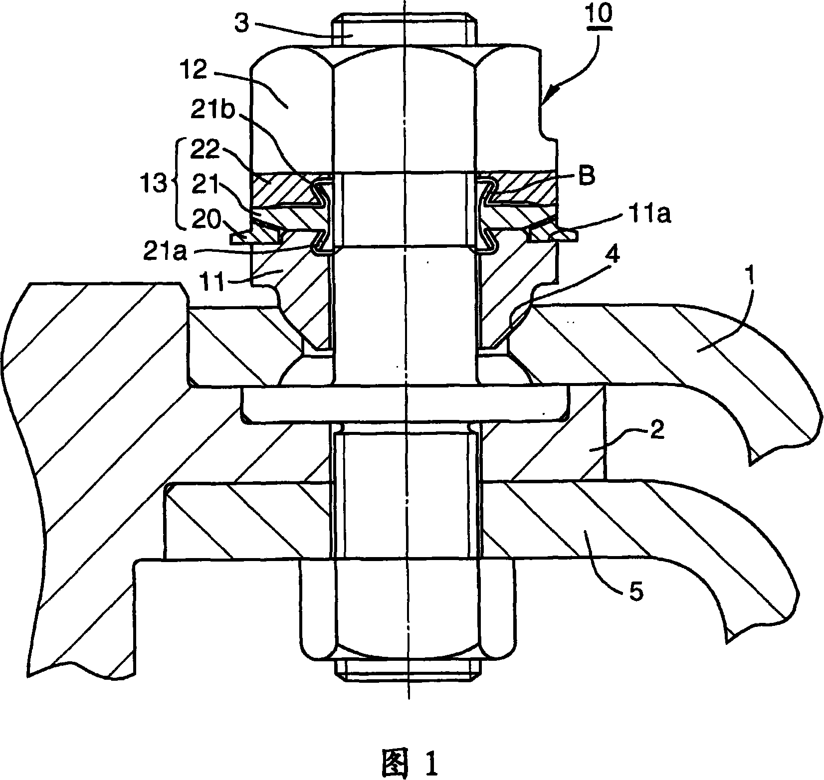
[0100] (Example 1)-Figure 1, Figure 18
[0101] In Embodiment 1 of the present invention, as shown in FIGS. 1 and 18, the ring assembly 13 of the axial force management nut assembly 10 has the first axial force in the order from the seat member 11 to the tightening nut 12 The management ring 20, the elastic deformation ring 21 and the axial force transmission ring 22. The first axial force management ring 20 applies an appropriate bolt axis to the bolt 3 between the stepped portion (step-like retreat portion) 11a of the outer peripheral portion of the seat member 11 and the tapered portion 21c of the outer peripheral portion of the elastic deformation ring 21 The stage before the force is installed freely to rotate. The axial force transmission ring 22 and the elastically deformable ring 21 are in contact with each other at the outer peripheral part of the two rings, and there is a gap in the inner peripheral part of the two rings.
[0102] The ring assembly 13 does not have an ex...
Embodiment 2
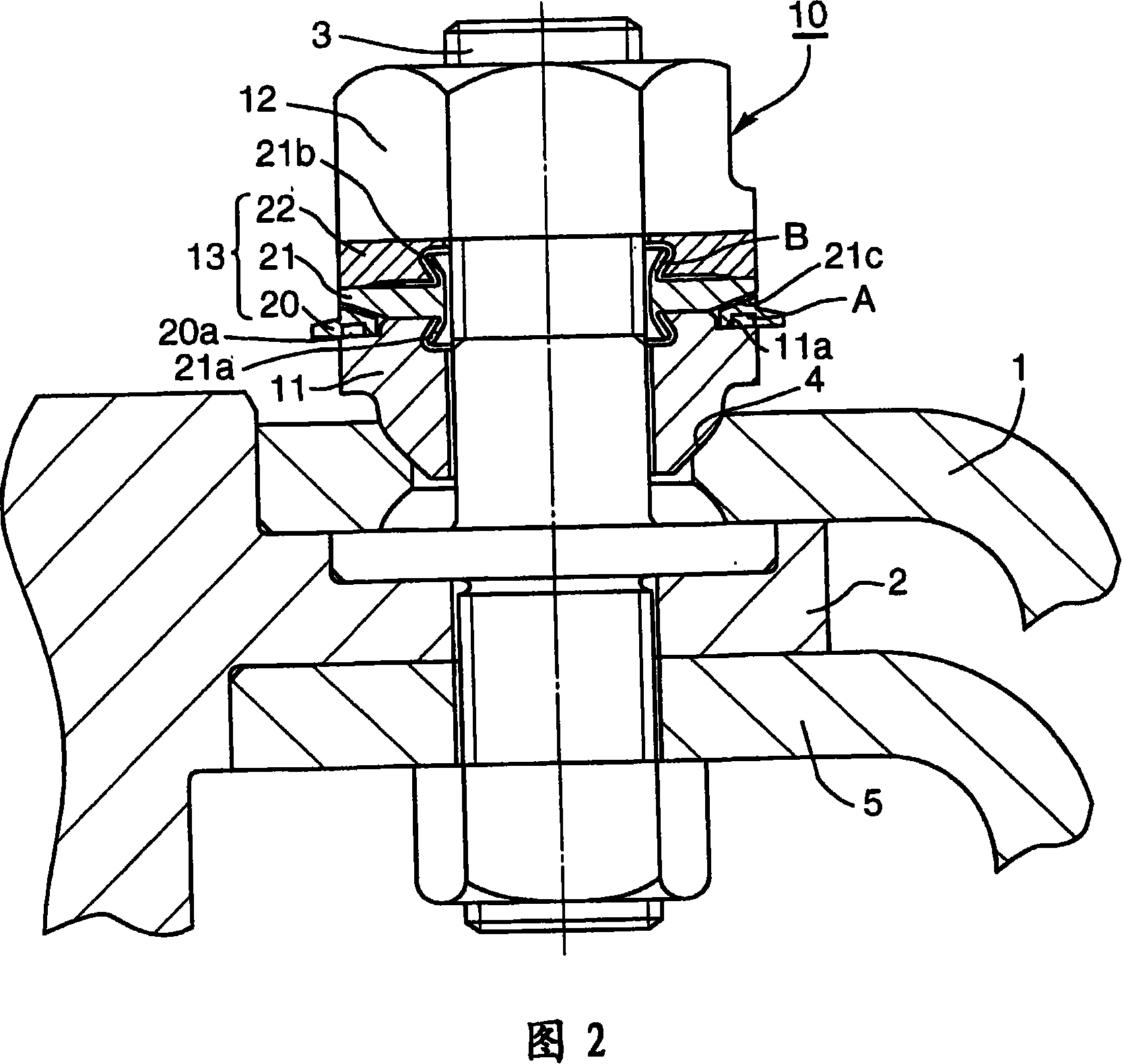
[0108] (Example 2)-Figure 2, Figure 18
[0109] The embodiment 2 of the present invention is an embodiment in which the groove 20a as the excess axial force detection structure A is added to the embodiment 1 of the present invention.
[0110] In the second embodiment of the present invention, as shown in FIGS. 2 and 18, the ring assembly 13 of the axial force management nut assembly 10 has a first axial force management ring in the order from the seat member 11 to the tightening nut 12 20. Elastic deformation ring 21 and axial force transmission ring 22. The first axial force management ring 20, in the space between the stepped portion (stepped retreat portion) 11a of the outer peripheral portion of the seat member 11 and the tapered portion 21c of the outer peripheral portion of the elastically deformable ring 21, apply an appropriate bolt in the axial direction The stage before the force is installed with free rotation. The axial force transmission ring 22 and the elastically de...
Embodiment 3
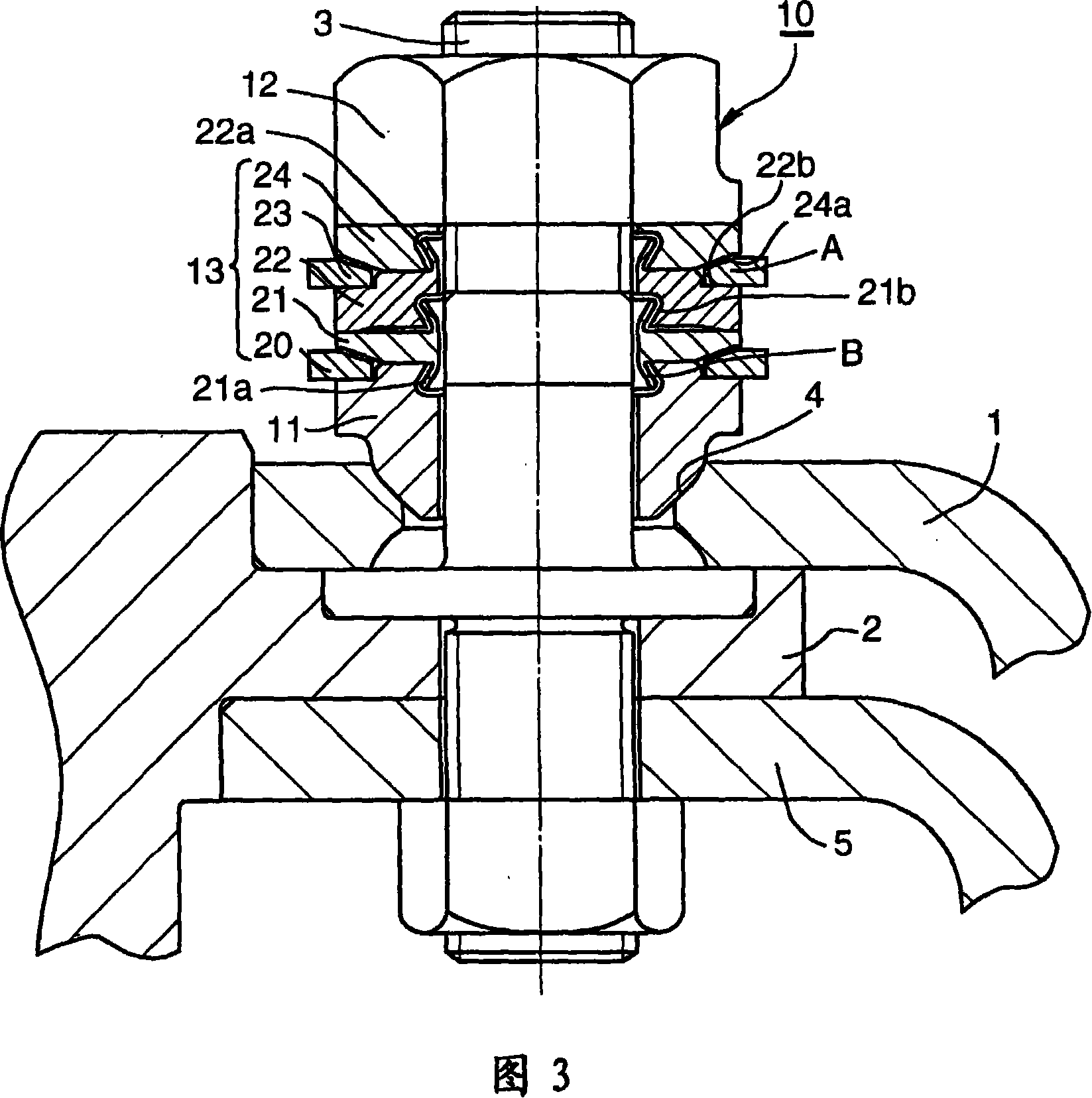
[0119] (Example 3)-Figure 3, Figure 18
[0120] The third embodiment of the present invention is an embodiment in which the second axial force management ring 23 as the excess axial force detection structure A is added to the first embodiment of the present invention.
[0121] In the third embodiment of the present invention, as shown in FIGS. 3 and 18, the ring assembly 13 of the axial force management nut assembly 10 has a first axial force management ring in the order from the seat member 11 to the tightening nut 12 20. Elastic deformation ring 21 and axial force transmission ring 22. The axial force transmission ring 22 and the elastically deformable ring 21 are in contact at the outer circumference of the two rings, and there is a gap in the inner circumference of the two rings.
[0122] The ring assembly 13 of the axial force management nut assembly 10 also includes: rotating before the bolt axial force becomes an excess axial force larger than the appropriate axial force, a...
PUM
 Abstract
Description
Claims
Application Information
 - R&D
- Intellectual Property
- Life Sciences
- Materials
- Tech Scout
- Unparalleled Data Quality
- Higher Quality Content
- 60% Fewer Hallucinations
Browse by: Latest US Patents, China's latest patents, Technical Efficacy Thesaurus, Application Domain, Technology Topic, Popular Technical Reports.
© 2025 PatSnap. All rights reserved.Legal|Privacy policy|Modern Slavery Act Transparency Statement|Sitemap|About US| Contact US: help@patsnap.com