Eureka AIR delivers breakthrough ideas for toughest innovation challenges, trusted by R&D personnel around the world.

Brake band holder

A brake band and brake device technology, applied in the direction of brake types, drum brakes, manufacturing tools, etc., can solve the problems of occupying a large space, and achieve the effects of saving space, reducing repair costs, and compact installation

Inactive Publication Date: 2008-01-02
DOLMAR
View PDF4 Cites 2 Cited by
  • Summary
  • Abstract
  • Description
  • Claims
  • Application Information

AI Technical Summary

Problems solved by technology

However, this is only possible if there is sufficient lateral distance between the active brake band bracket and the shaft
Therefore, the installation of the active brake band bracket takes up a lot of space in the active surface

Method used


Image

  • Brake band holder
  • Brake band holder
  • Brake band holder

Examples


Embodiment Construction

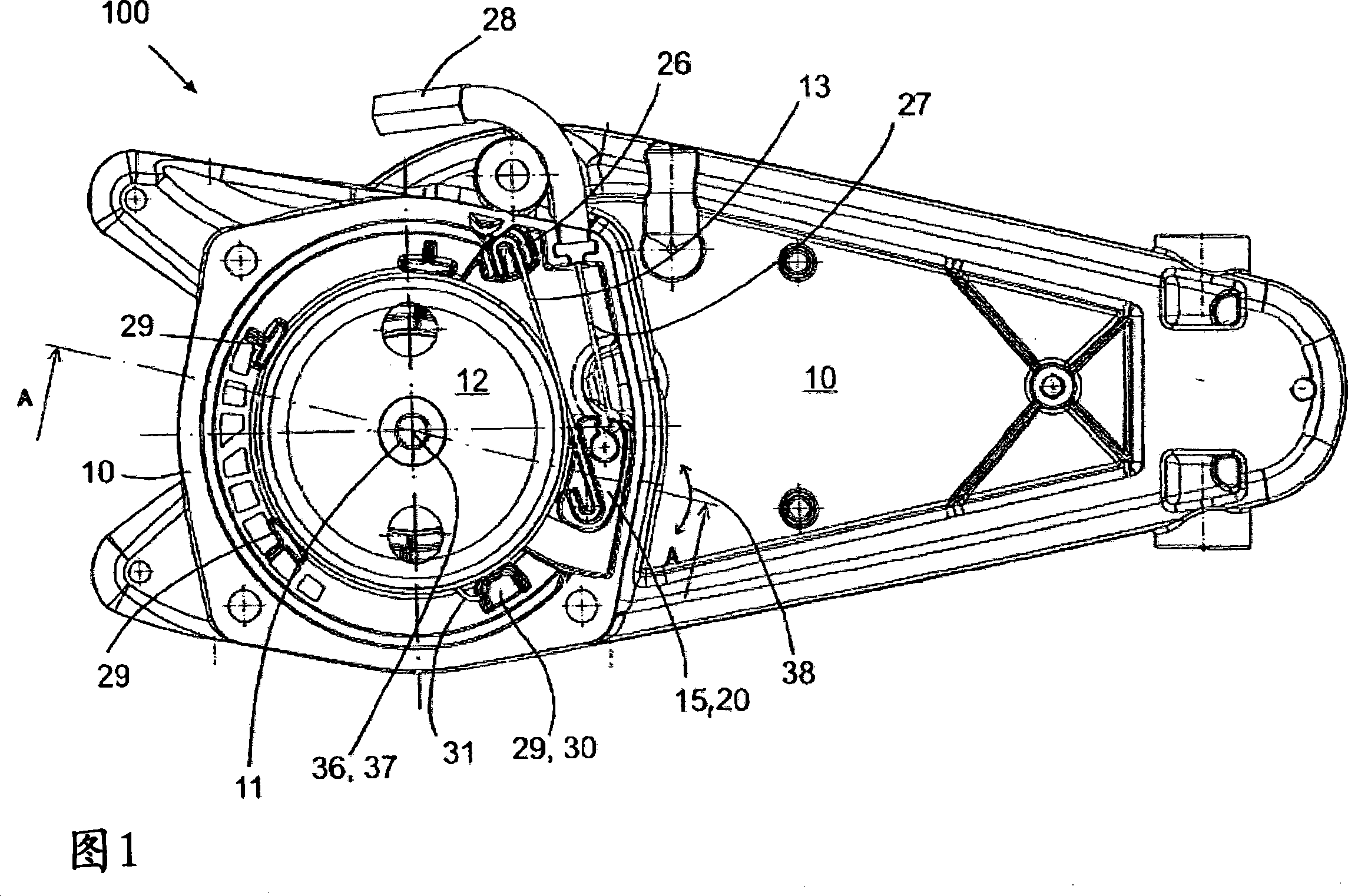
[0030]In FIG. 1 , the brake device 100 has a housing 10 . The associated hand tool with electric motor and starter unit is attached to this housing. However, the braking device 100 is shown without these components for simplicity. In FIG. 1 , the braking device 100 according to the invention is in a rest position, wherein the brake band 13 is under tension via the movable brake band support 15 . In order to obtain a braking effect on the shaft 11 , a brake band 13 is wound around a brake drum 12 connected to the shaft 11 . Also to ensure that the brake band 13 remains approximately in place in the operating position, radial guide rails 29 are arranged circumferentially around the brake drum 12 . At least one axial guide 30 is provided to cooperate with a protuberance 31 on the brake band 13 . In the present case, these axial guides 30 also serve as radial guides 29 for the brake band 13 . The brake band 13 is also shown under tension created by the fixed brake band support...


PUM


Abstract

The present invention relates to a braking device (100) for braking or stopping the working tool (35) especially the axle of the chain saw, the hedge shear, etc. The braking device (100) is provided with a braking band (13) which surrounds at least one part of the area of the axle (11), wherein the braking band (13) forms the useful surface (14); and two braking band brackets (15, 26), the braking band (13) can be tensioned / relaxed by the braking band bracket, wherein at least one brake band bracket (15) is constructed to be movable. The bracket of the movable brake band is disposed that the bracket needs little space in the braking device, so the bracket is suggested that at least one braking band bracket (15) is installed at the outside of the useful surface (14) of the braking band (13) in order that the bracket rotates around the vortex line of the rotational axle or the approximate parallel axial cord or axle (11), and / or that the bracket can move in the straight line direction in the plane surface which is approximate upright to the axle (11).

Description

technical field [0001] The invention relates to a braking device for braking or immobilizing the shaft of a work tool, including in particular a chainsaw, a shear blade, a rotary head and the like. For example, such braking devices may be used in the housing of hand-held tools such as chainsaws, power shears, rotary lawn mowers or the like. Here, the work tool in question must be able to slow down and stop quickly to prevent any possible injury to the operator of the tool. For this purpose, the braking device has a braking band which at least partially surrounds the region of the shaft, the braking band forming an effective surface. Here, the axis in question is to be understood as the axis of the motor or the tool. The brake device is also equipped with two brake band supports, via which the brake band can be tensioned, and at least one of the brake band supports is designed to move so that tension can thereby be applied to the brake band. Background technique [0002] I...

Claims


Application Information

Patent Timeline
Patent Type & Authority Applications(China)
IPC IPC(8): F16D49/08B27G19/00
CPCF16D49/08B27B17/083
Inventor M·耶瑟C·齐格斯
Owner DOLMAR
Why Eureka
Eureka Blog
Learn More