Fan operating control system

A technology of operation control and fan, applied in the direction of pump control, non-variable pump, machine/engine, etc., can solve the problem of large operation noise

Inactive Publication Date: 2008-01-02
ASUSTEK COMPUTER INC
View PDF0 Cites 2 Cited by
  • Summary
  • Abstract
  • Description
  • Claims
  • Application Information

AI Technical Summary

Problems solved by technology

As the voltage of said rated power is usually as high as 12 volts, it will drive the fan to run at a higher speed and generate a lot of running noise

Method used


Image

  • Fan operating control system
  • Fan operating control system
  • Fan operating control system

Examples


Embodiment Construction

[0023] Because the fan operation control system provided by the present invention can be widely used in various systems, devices or facilities that can be combined with fans, such as computer systems, processing cooling control systems, air-conditioning systems, etc., and its combination implementations are too numerous to enumerate, so in This will not go into details one by one, but only one of the preferred embodiments and two application examples derived from the preferred embodiment are listed for specific description.

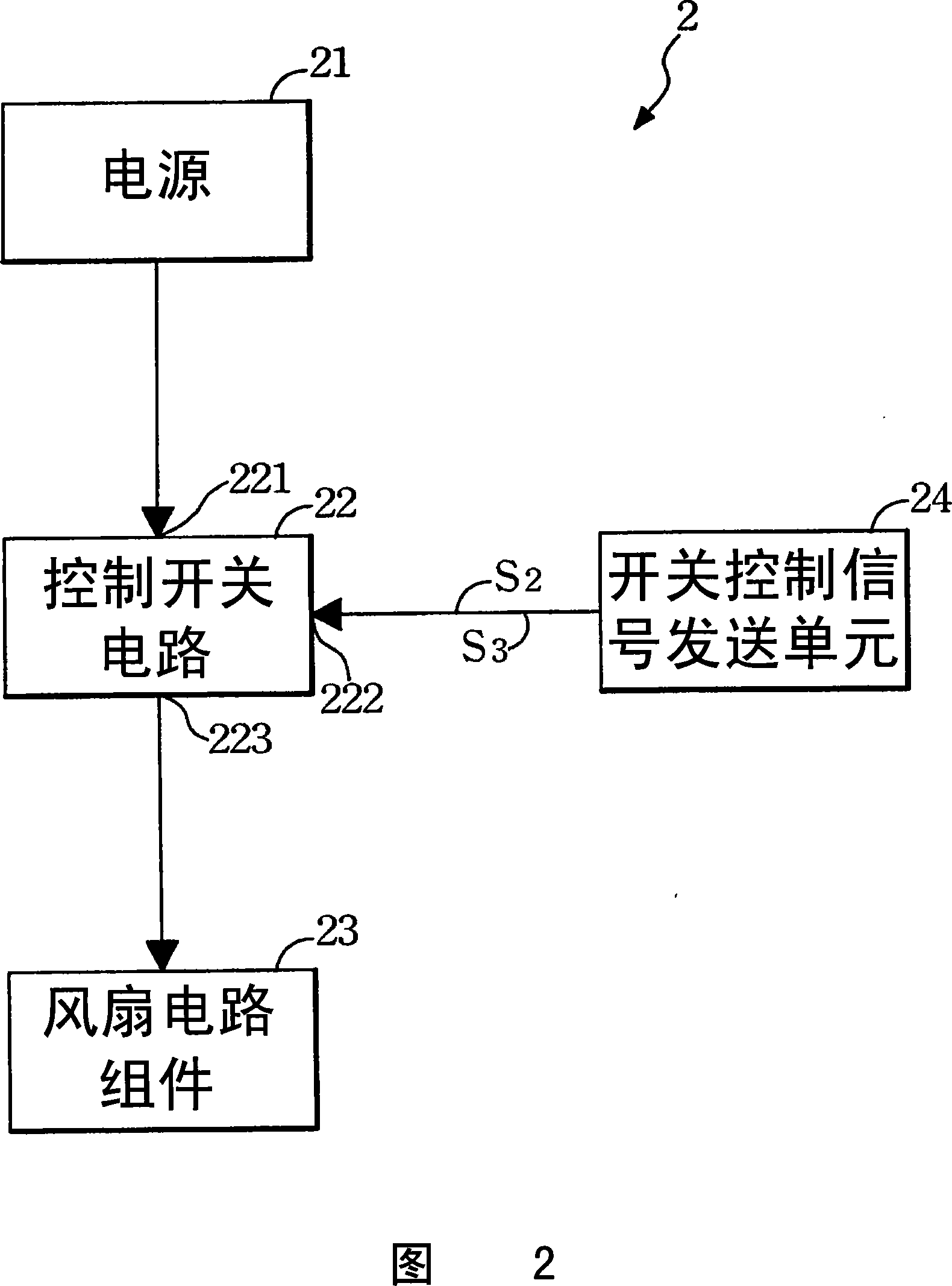
[0024] Please refer to FIG. 2 , which is a block diagram showing a basic circuit of a preferred embodiment of the present invention. As shown in the figure, a fan operation control system 2 includes a power supply 21 , a control switch circuit 22 , a fan circuit assembly 23 and a switch control signal sending unit 24 . Wherein, the power supply 21 can be a power supply, and the control switch circuit 22 is electrically connected to the power supply 21 , t...


PUM


Abstract

The invention discloses a fan operating controlled system, which is characterized by the following: comprising a electrical source, a controlling switch circuit, a switch controlled signal sending unit and a fan circuit component; sending a nominal electric force with power; electric-connecting the controlled switch circuit to the power; electric-connecting the switch controlled signal sending unit system to the controlled switch circuit; sending a power controlled signal to the controlled switch circuit; electric-connecting the fan circuit element to the controlled switch circuit; passing the nominal electric force through the controlled switch circuit; adjusting to a controlled power; sending to the circuit component of the fan; driving at least one fan to rotate in the fan circuit component; controlling the controlled power with the power controlled signal.

Description

technical field [0001] The invention relates to a fan operation control system, in particular to a fan operation control system which can control the fan to reduce the noise generated by the operation during an initial operation stage. Background technique [0002] In general electronic devices, in order to improve their operating efficiency, most of them are equipped with a heat dissipation system, so as to reduce the high temperature generated by the internal components of the electronic device during operation, so as to improve the overall operating performance. Especially for computer devices, in order to effectively increase the operating efficiency of various electronic components, most of them are equipped with fans and heat dissipation components. Among them, the heat dissipation components usually use heat conduction to directly absorb the heat energy generated by the operation of electronic components, and then use the operation of the fan to generate convective ai...

Claims


Application Information

Patent Timeline
Patent Type & Authority Applications(China)
IPC IPC(8): F04D27/00
Inventor 张胜雄陈启隽陈雅琴
Owner ASUSTEK COMPUTER INC
Why Eureka
Try Eureka