Heavy duty pneumatic tire

A technology of pneumatic tires and tires, which is applied in the direction of heavy tires, reinforcement layers of pneumatic tires, tire parts, etc., and can solve problems such as the decrease in tire durability

Active Publication Date: 2008-01-02
SUMITOMO RUBBER IND LTD
View PDF4 Cites 2 Cited by
  • Summary
  • Abstract
  • Description
  • Claims
  • Application Information

AI Technical Summary

Problems solved by technology

The increase in size leads to a decrease in the durability of the tire

Method used


Image

  • Heavy duty pneumatic tire
  • Heavy duty pneumatic tire

Examples


Embodiment 1

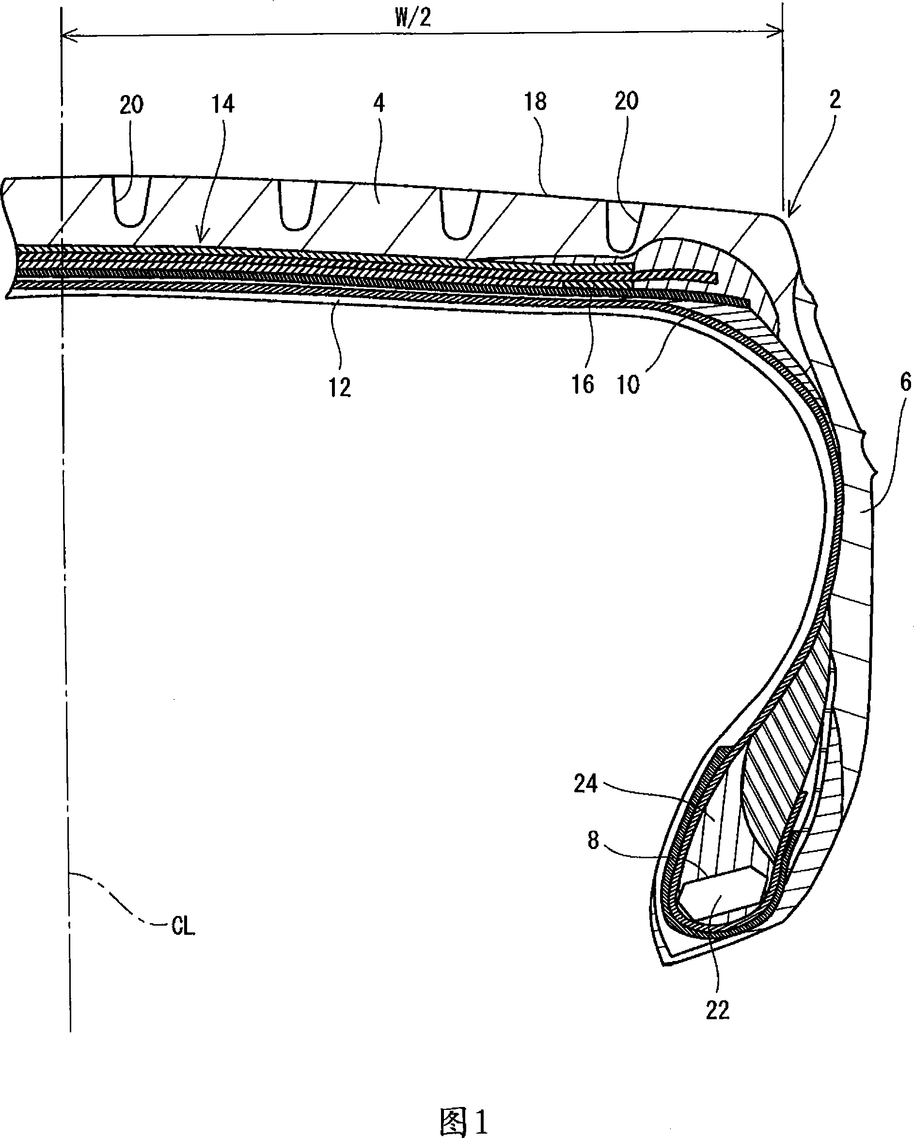
[0050] A truck tire having the structure shown in Figs. 1 and 2 was obtained. The tire specification is "435 / 45R22.5". This tire has a 374mm wide tread. The tread has grooves 13.5 mm deep. The ratio of the width W1 to the width W of the first layer is 99.4%. The ratio of the width W2 to the width W of the second layer was 95.7%. The ratio of the width W3 to the width W of the third layer is 77%. The distance La is 7mm. The first layer comprises steel cords at an angle of +18° to the circumferential direction. The second and fourth layers consisted of steel cords at an angle of -18° to the circumferential direction. The third layer comprises steel cords extending substantially in the circumferential direction. The tire has a hard rubber layer formed from a crosslinked rubber composition. The rubber composition comprises 100 parts by weight of natural rubber, 70 parts by weight of carbon black, 2.0 parts by weight of sulfur, 2.0 parts by weight of a vulcanization acceler...

Embodiment 4~6

[0052] Tires according to Examples 4 to 6 were obtained in the same manner as in Example 1 except that the thickness of the hard rubber layer was set as shown in Table 1 below.

Embodiment 3 and 7~8

[0054] Tires according to Examples 3 and 7 to 8 were obtained in the same manner as in Example 1, except that a second layer having a short width W2 was provided, and the distance La was set as shown in Table 1 below.


PUM


Abstract

A tire 2 has a belt 14 and a hard rubber layer 16. The belt 14 has a first ply 26, a second ply 28, a third ply 30 and a fourth ply 32. A width W3 of the third ply 30 is smaller than a width W1 of the first ply 26 and a width W2 of the second ply 28, and 75% of a width of a tread. Each of the plies 26, 28, 30, 32 has a steel cord. The first ply 26 and the second ply 28 construct a cross-ply structure. A cord of the third ply 30 is wound spirally. The third ply 30 has what is referred to as a jointless structure. The hard rubber layer 16 is positioned between the first ply 26 and the second ply 28, and outward of the third ply 30 in an axial direction. A complex elastic modulus of the hard rubber layer 16 is equal to or greater than 30 MPa.

Description

[0001] This application claims priority to Patent Application No. 2006-177519 filed in Japan on June 28, 2006, the entire contents of which are incorporated herein by reference. technical field [0002] The present invention relates to load pneumatic tires to be mounted on load vehicles such as trucks and buses. More specifically, the invention relates to tires having a carcass of radial construction. Background technique [0003] Tires with radial construction are known. JP-A No. 2-141309 has disclosed a truck tire having a belt layer including cords extending in the circumferential direction. US Patent No. 6,082,425 (JP-A No. 2000-504655) has disclosed a radial load tire having a belt layer including cords extending in the circumferential direction and a belt layer having a bias structure. US Patent No. 6,401,778 (JP-A No. 2001-522748) has disclosed a radial load tire having a belt layer including cords extending in the circumferential direction and a belt layer having a...

Claims


Application Information

Patent Timeline
Patent Type & Authority Applications(China)
IPC IPC(8): B60C9/18
CPCB60C2009/1842B60C9/2006B60C2200/06B60C9/185B60C9/2204B60C2009/1871Y10T152/10783Y10T152/10792
Inventor 万野明应矢幸秀吉川荣明
Owner SUMITOMO RUBBER IND LTD
Why Eureka
Try Eureka