
True logarithm amplifier

A technology of logarithmic amplifier and limiting amplifier, applied in the field of true logarithmic amplifier, large dynamic, low power consumption true logarithmic amplifier, high precision, can solve the problems of large static power consumption, large volume, difficult debugging, etc. Reduced power consumption, reduced size, and ease of mass production

Inactive Publication Date: 2007-12-26
NO 24 RES INST OF CETC
View PDF0 Cites 5 Cited by
  • Summary
  • Abstract
  • Description
  • Claims
  • Application Information

AI Technical Summary

Problems solved by technology

[0004] The technical problem to be solved by the present invention is to invent a novel true logarithmic amplifier structure, which is realized by cascading the continuous detection type logarithmic amplifier, limiting amplifier and multiplier, which solves the problem of traditional large dynamic Problems of high static power consumption, large volume and difficult debugging of true logarithmic amplifier

Method used


Image

  • True logarithm amplifier
  • True logarithm amplifier
  • True logarithm amplifier

Examples


Embodiment Construction

[0026] The specific implementation manners of the present invention are not limited to the following description, and are now further described in conjunction with the accompanying drawings.

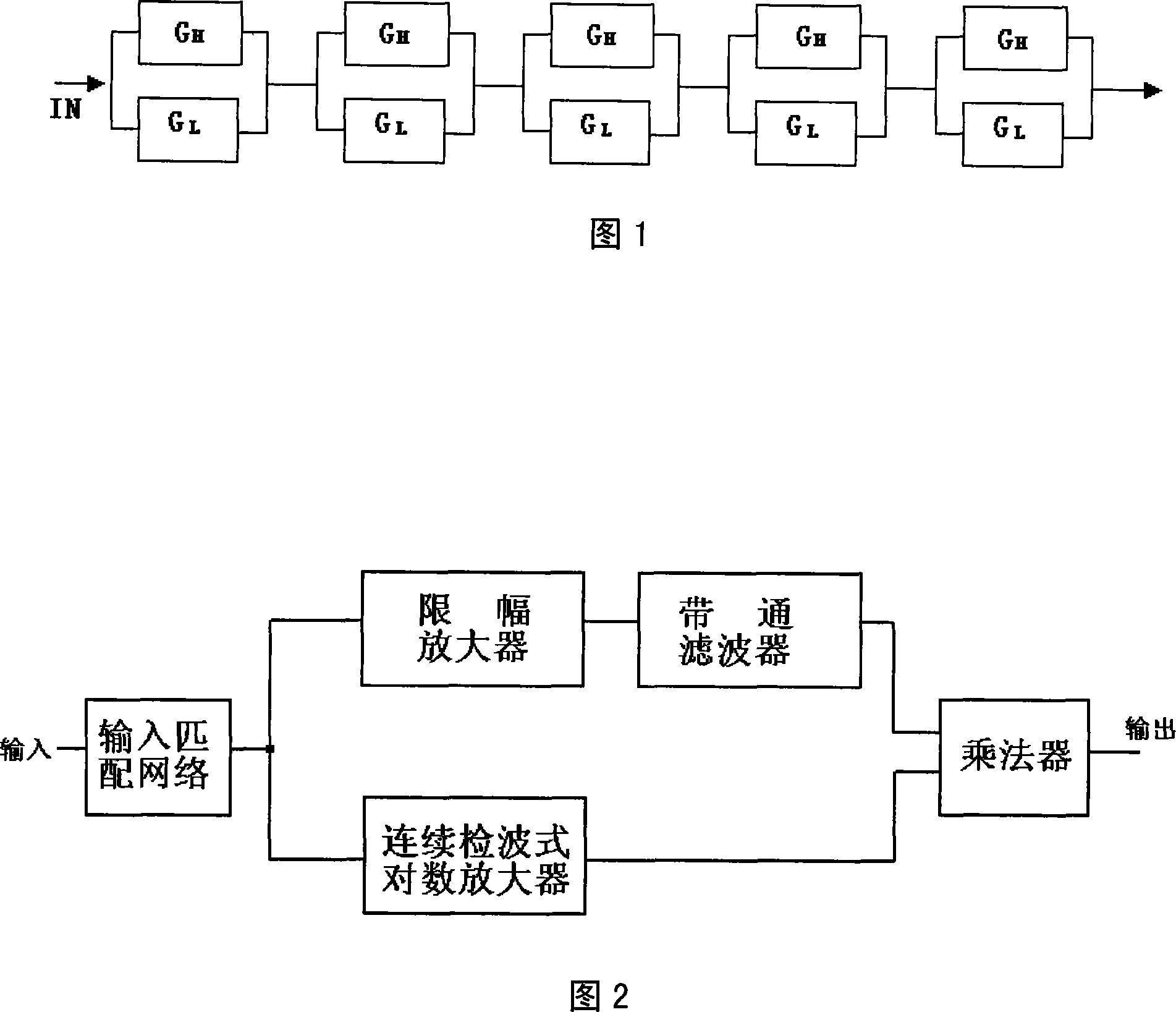
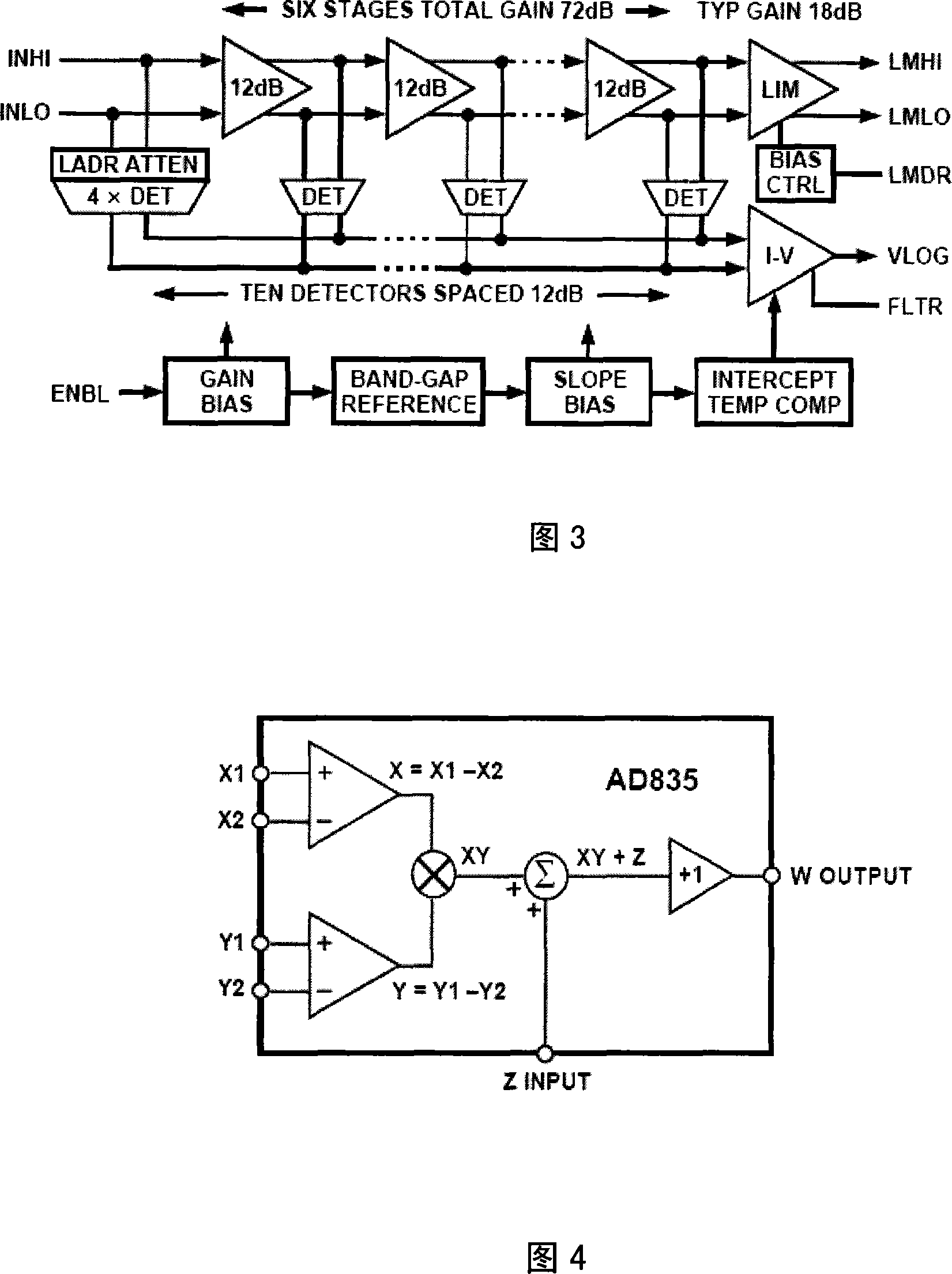
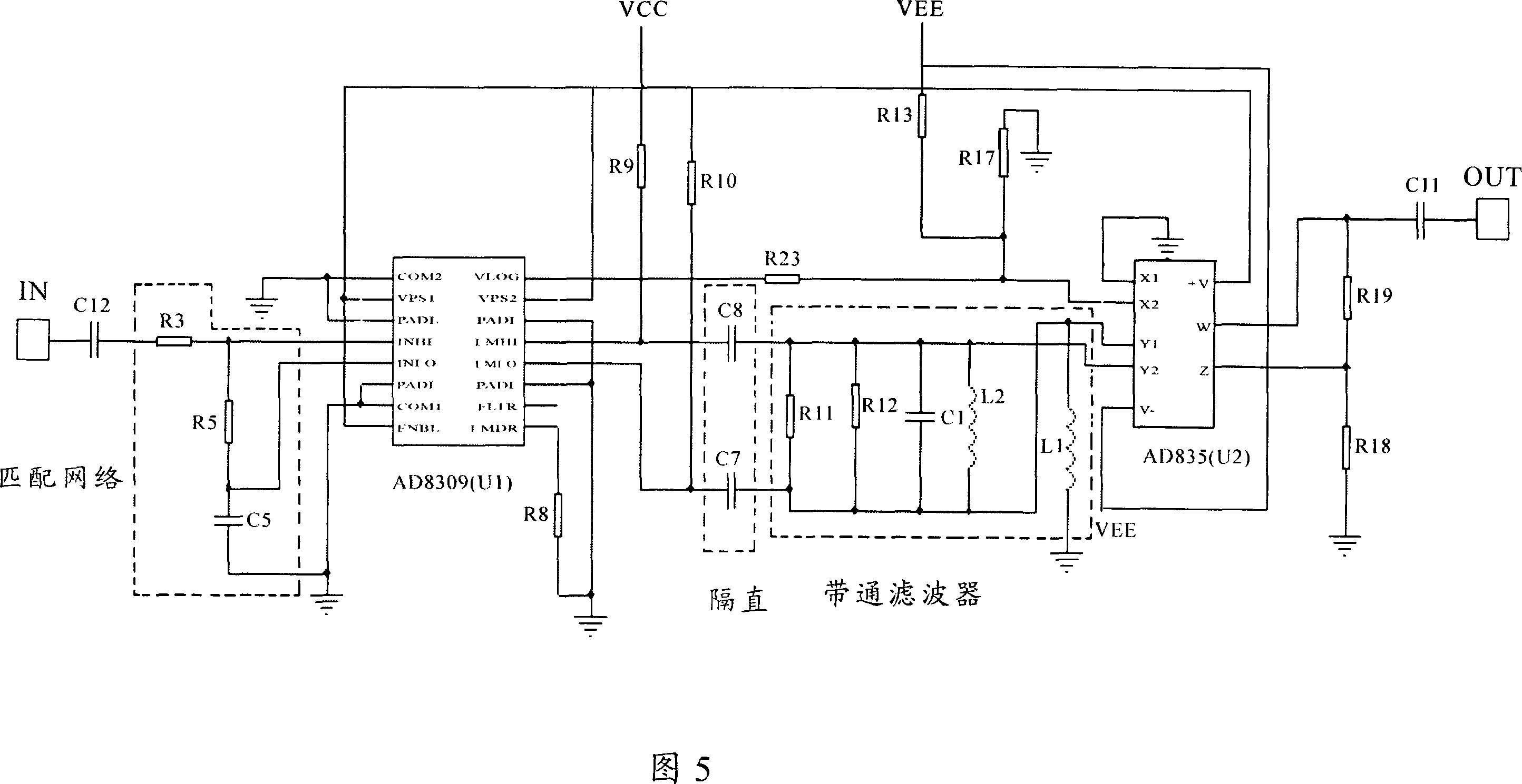
[0027] The circuit block diagram of the present invention is as shown in Figure 2, and the true logarithmic amplifier circuit of the present invention comprises an input matching network, a limiting amplifier, a bandpass filter, a limiting amplifier / continuous detection type logarithmic amplifier and a multiplication device.

[0028] The working principle of the technical solution of the present invention is:

[0029] The input signal is divided into two paths: one path enters the limiting amplifier circuit to obtain an output signal with a stable amplitude, the signal frequency is the same as the input signal, and the phase information of the input signal is retained (Formula 1); the other path enters the continuous detection logarithmic amplifier , resulting in a video signal that is ...


PUM


Abstract

The amplifier includes an input matching network, a limiting amplifier, a band-pass filter, a limiting amplifier / consecutive detection type logarithmic amplifier, and a multiplier. The designed true logarithmic amplifier (TLA) in new structure solves issues of traditional large dynamic TLA: large quiescent power dissipation, large volume, and difficult debugging. Volume of the produced TLA is 38X20X5mm, and source current is 40mA / +-5V. The produced TLA with large dynamic range, high precision, and low power waste is applicable to areas of communication, radar, sonar and electronic countermeasure etc widely.

Description

(1) Technical field [0001] The invention relates to a true logarithmic amplifier, in particular to a large dynamic, high precision, low power consumption true logarithmic amplifier, which is directly applied in the fields of communication, radar, sonar and electronic countermeasures. (2) Background technology [0002] At present, the traditional implementation method of true logarithmic amplifier is: a dual-gain circuit structure is adopted, and several stages of dual-gain units (TLA) are cascaded to obtain a high-precision, large dynamic true logarithmic amplifier, as shown in Figure 1. The dual gain unit (TLA) consists of a high gain limiting amplifier and a unity gain amplifier G L and the output stage. [0003] In the traditional true logarithmic amplifier circuit structure, in order to ensure the unity gain amplifier G L The gain is 1 throughout the dynamic range of the input signal, and the quiescent operating current of the unit circuit is relatively large (usually ...

Claims


Application Information

Patent Timeline
Patent Type & Authority Applications(China)
IPC IPC(8): H03F1/02H03F3/00
Inventor 庞佑兵唐万军刘登学王智玮冉劲松
Owner NO 24 RES INST OF CETC
Learn More