Eureka AIR delivers breakthrough ideas for toughest innovation challenges, trusted by R&D personnel around the world.

Heat storage type vertical metal magnesium reducing furnace

A metal magnesium reduction furnace technology, applied in the field of regenerative vertical metal magnesium reduction furnace, can solve the problems of high exhaust gas temperature, easy dust accumulation in the reduction tank, insufficient fuel combustion, etc., to reduce the exhaust gas temperature, burn Unique method, the effect of improving combustion efficiency

Inactive Publication Date: 2007-12-26
宁夏华源冶金实业有限公司 +1
View PDF0 Cites 5 Cited by
  • Summary
  • Abstract
  • Description
  • Claims
  • Application Information

AI Technical Summary

Problems solved by technology

[0002] The traditional metal magnesium reduction furnace generally adopts the structure of returning heat to heat the reduction tank. The flame and flue gas in the reduction furnace of this traditional structure enter the furnace through the fire retaining wall, pass through the reduction tank from top to bottom, and quickly pass through the fire suction hole. Exhausted from the furnace, the exhaust gas temperature is as high as about 1200°C, which cannot be recycled well, and the energy waste is serious
In addition, the traditional metal magnesium reduction furnace uses raw coal as fuel, which has low combustion efficiency and serious pollution. Moreover, this combustion method leads to uneven temperature in the furnace chamber of the metal magnesium reduction furnace, and inflexible control of the combustion temperature, resulting in a short service life of the reduction tank. The quality of finished magnesium metal produced is not high
[0003] The existing magnesium reduction furnace has a large useless space in the furnace, and the supporting wall of the reduction tank occupies a large space, which affects heat conduction; It is easy to deform under high temperature and high vacuum conditions, which hinders loading and unloading, and ultimately affects the service life: horizontal filling makes it difficult to pack the material, and often occurs that the filling is not solid and affects the uniformity of heating, thereby affecting the uniformity of the reaction; During the magnesium smelting process, the upper part of the reduction tank is easy to accumulate dust, which is serious for a long time and affects heat conduction; the heating of the reduction furnace mainly uses coal or producer gas for direct combustion, and there is no dust removal facility; the gas uses a simple burner with low technical content. Insufficient combustion produces a large amount of harmful gas and industrial dust, polluting the environment
When loading, workers use long rods to push in the reaction materials, and when discharging, they use long rods to take out the materials bit by bit. The loading and unloading of materials is carried out at the end of the reduction tank. The operation time is long, the environment is harsh, and the labor intensity is high. Concentration of personnel, prone to safety accidents

Method used


Image

  • Heat storage type vertical metal magnesium reducing furnace

Examples


Embodiment Construction

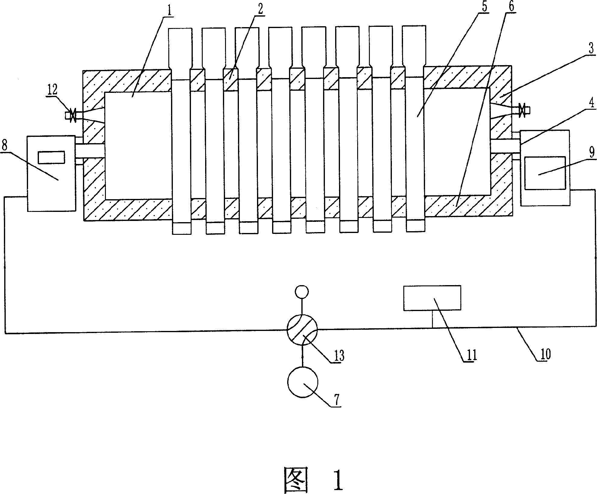
[0024] A regenerative vertical metal magnesium reduction furnace is composed of a hearth 1, a furnace roof 2, a furnace wall 3, a burner 4, a reduction tank 5, a furnace bottom regenerator 6 and a fan 7, as shown in Figure 1: There are several pairs of double regenerative burners 4 correspondingly arranged at the bottom of both ends in the furnace width direction, forming a regenerator I8 and a regenerator II9 at the bottom of the furnace at both ends, and installing two reversing valves 13 at each end, and reversing The valve 13 is connected to the regenerator I8, the regenerator II9 and the fan 7 through the pipeline 10 outside the furnace and the reversing control system 11. The reduction tank 5 in the furnace 1 is arranged in a vertical manner, with the upper part feeding and the lower part discharging slag. The reduction tanks 5 in the furnace 1 are divided into four rows on average, each row of reduction tanks 5 is spaced at a certain distance, and two pairs of the air an...


PUM


Abstract

This invention relates to a Mg recovery furnace with a vertical recovery tank composed of a hearth, a roof, a wall, burners, a recovery tank, bottom storage chambers and a fan charactering in arranging several pairs of double-storage burners along the bottom of two ends on the furnace width direction, forming storage chamber1 and 2 on the bottom of the two ends, installing two directional valves at either end, the directional valves, the storage chamber 1 and 2 and the fan are connected with a directional control system by exterior pipelines, applying a vertical mode to arrange the recovery tank in the hearth and feeding from the top and discharging from the bottom, which costs less energy, temperature in the furnace is the uniform and burning mode is exclusive.

Description

technical field [0001] The invention relates to a metal magnesium reduction furnace, in particular to a regenerative vertical metal magnesium reduction furnace with a vertical reduction tank. Background technique [0002] The traditional metal magnesium reduction furnace generally adopts the structure of returning heat to heat the reduction tank. The flame and flue gas in the reduction furnace of this traditional structure enter the furnace through the fire retaining wall, pass through the reduction tank from top to bottom, and quickly pass through the fire suction hole. Exhausted from the furnace, the exhaust gas temperature is as high as about 1200 ° C, which cannot be recycled well, and the energy waste is serious. In addition, the traditional metal magnesium reduction furnace uses raw coal as fuel, which has low combustion efficiency and serious pollution. Moreover, this combustion method leads to uneven temperature in the furnace chamber of the metal magnesium reduction...

Claims


Application Information

Patent Timeline
Patent Type & Authority Applications(China)
IPC IPC(8): F27B14/00
Inventor 辛卫亚李文胜
Owner 宁夏华源冶金实业有限公司
Why Eureka
Eureka Blog
Learn More