A percussion drill possessing magnetometric percussion arrangement

An impact mechanism and impact drill technology, applied in the field of impact drills, can solve the problems of loss, large vibration and noise, heat generation, etc., achieve long service life, reduce vibration and noise, and save lubricating oil

Inactive Publication Date: 2007-12-26
ZHEJIANG UNIV
View PDF0 Cites 7 Cited by
  • Summary
  • Abstract
  • Description
  • Claims
  • Application Information

AI Technical Summary

Problems solved by technology

Such a structure that utilizes the shape of the end faces to engage and generate an impact force will cause heat generation and energy loss due to friction, and at the same time, vibration and noise will be very large

Method used


Image

  • A percussion drill possessing magnetometric percussion arrangement
  • A percussion drill possessing magnetometric percussion arrangement

Examples


Embodiment Construction

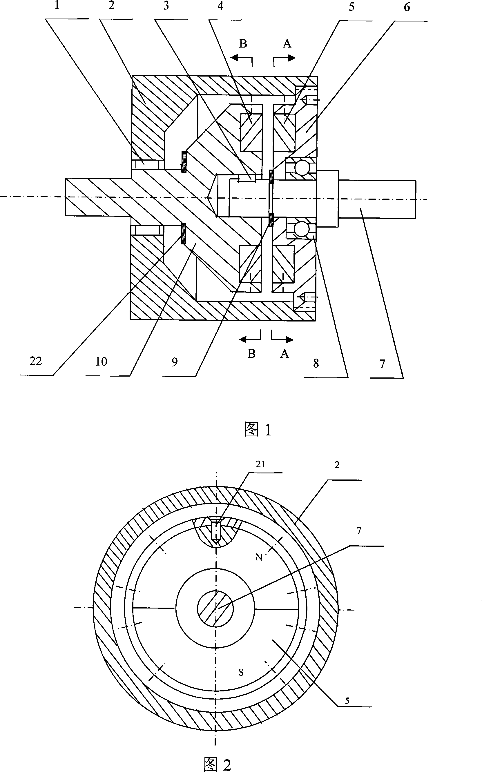
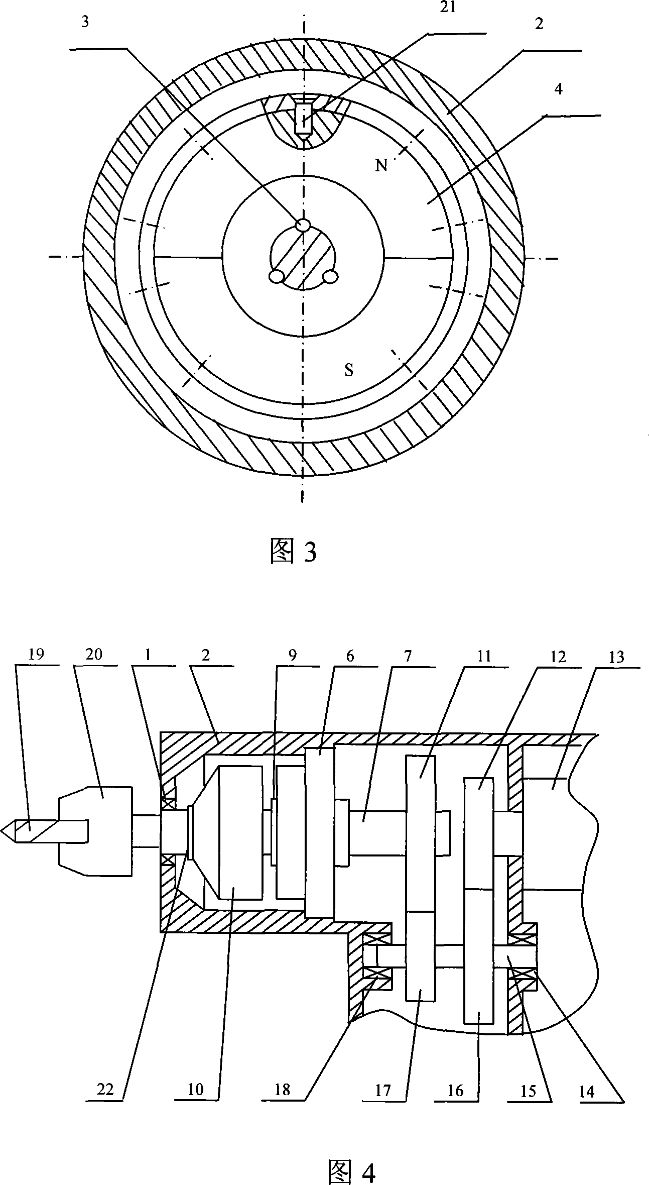
[0016] As shown in Figures 1 and 4, the present invention includes a housing 2, a motion transmission mechanism consisting of a motor 13, a drive gear 11, a motor gear 12, an intermediate gear 16 and an intermediate pinion 17, an impact mechanism and a drill chuck 20. The impact mechanism is a magnetic impact mechanism, and the small end shaft of the conical drive disc 10 is equipped with a rubber washer 22 to reduce the impact on the housing when the drive disc 10 moves axially. The small end shaft is supported by the first bearing 1 The front end of the housing 2 extends out of the housing 2, and the drill chuck 20 is installed. The large end surface of the conical drive disc 10 has an annular groove, and the first annular permanent magnet 4 is housed in the groove, and the support 6 is installed on the Inside the casing 2, the support 6 is threadedly connected with the casing 2, the drive shaft 7 is supported in the support 6 through the second bearing 8, and rotates relativ...


PUM


Abstract

The invention discloses a cable drilling tool with magnetic force percussion mechanism. It includes case, moving delivering structure, magnetic impact structure, and drill chuck. The small end surface axis using bearing supports at the front of case and extrudes out to install drill chuck. The large end surface has circle slot, where has circle permanent magnet. The driving axis is set in supporting base through bear. One end of driving shaft connects to center hole of driving disc through bond. A circle slot is set on the surface of supporting base where permanent magnet is installed. The permanent magnets would cause repulsive force and attractive force while rotating to make the driving disc move back and forth relative to driving shaft. The other end of driving shaft is connected to driving gear of driving structure. There are no energy consumption and no rigid impact in the invention. The useful life would be prolonged, and the lubricant will be saved. It also has no dust and noise during moving process.

Description

technical field [0001] The invention relates to a hand-held electric tool, in particular to an impact drill with a magnetic impact mechanism. Background technique [0002] For manual tool machines with impact drivers, such as impact hammers, impact drills, etc., in traditional impact drills of this type, the rotation of the motor reaches the main shaft through a gear transmission mechanism fixed on the shaft, and a drill is installed at one end of the main shaft. The chuck has a rotatable ratchet at the other end, and a ratchet on the end face. The rotatable ratchet rotates with the main shaft at the same time and can move axially together with the main shaft. A fixed ratchet is installed on the shell of the impact drill, and the fixed ratchet cannot rotate and move It is set opposite to the rotating ratchet, and there are ratchets on the end surface opposite to the rotating ratchet. When the motor rotates, the main shaft rotates through the gear transmission mechanism, and ...

Claims


Application Information

Patent Timeline
Patent Type & Authority Applications(China)
IPC IPC(8): B25D13/00
Inventor 冯培恩张惠邱清盈
Owner ZHEJIANG UNIV
Why Eureka
Try Eureka