
Full-digital non scratching switchover device and method

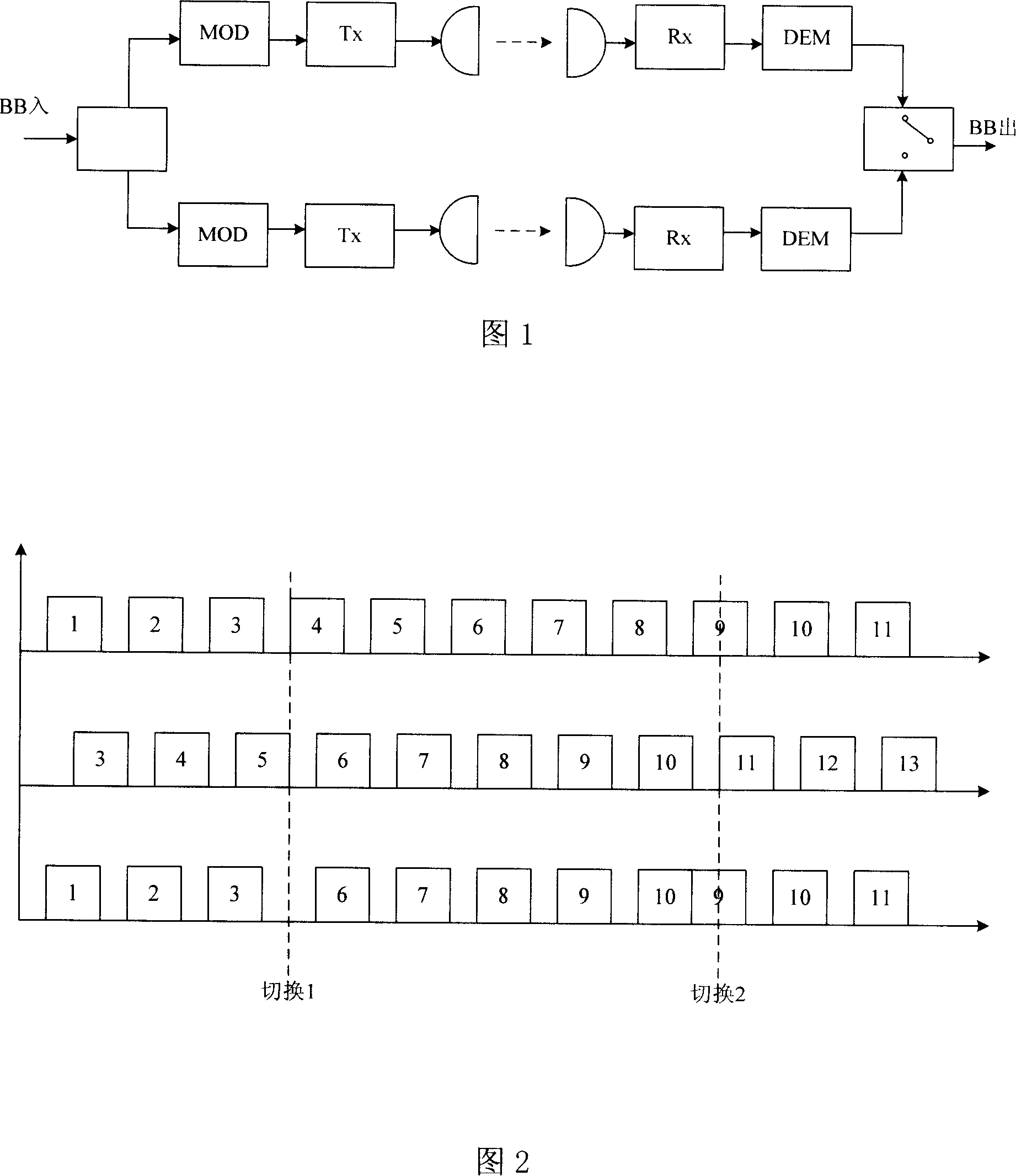
An all-digital, switching device technology, applied in digital transmission systems, electrical components, error prevention, etc., can solve problems such as long-term misalignment of code bits, low reliability, metastable phenomena, etc., to achieve cost savings, The effect of improving system reliability and performance

Inactive Publication Date: 2007-12-19
COMBA TELECOM SYST CHINA LTD
View PDF0 Cites 4 Cited by
  • Summary
  • Abstract
  • Description
  • Claims
  • Application Information

AI Technical Summary

Problems solved by technology

[0005] (2) Since the static delay circuit cannot be adjusted in real time, the main path of the elastic memory cannot be adjusted for delay. When the dynamic delay is too large, the code bits may not be aligned for a long time
[0007] (4) The input clock adjustment circuit is generated by the logic of the output clock, and has logic control of different clock domains, which is easy to cause the metastable phenomenon, and the reliability is not high

Method used


Image

  • Full-digital non scratching switchover device and method
  • Full-digital non scratching switchover device and method
  • Full-digital non scratching switchover device and method

Examples


Embodiment 1

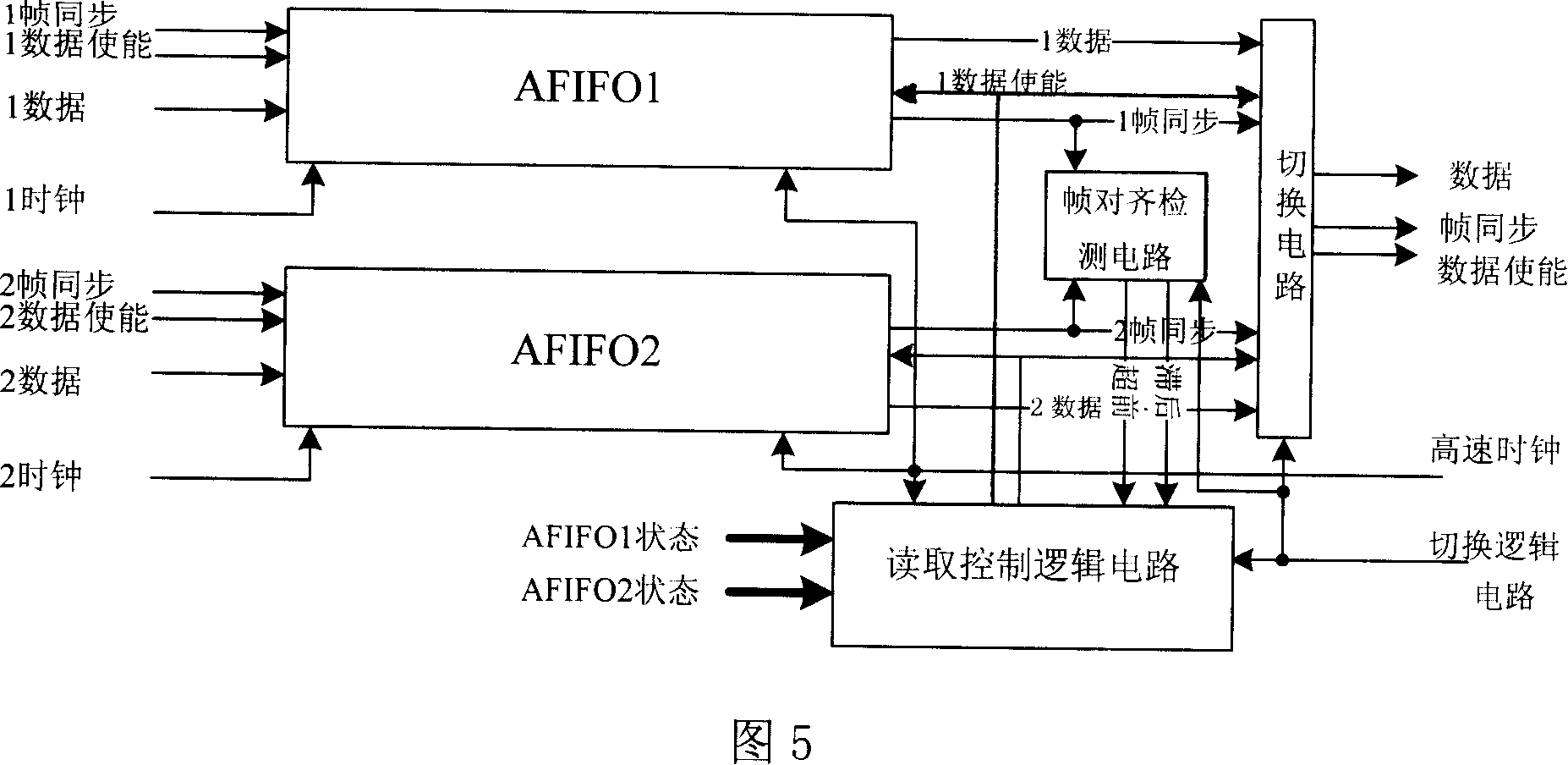
[0035] As shown in Figure 5, the fully digital damage-free switching device includes a working AFIFO1 circuit, a standby AFIFO2 circuit, a frame alignment detection circuit, a switching circuit, a read control logic circuit, a switching logic circuit, a high-speed clock, a working AFIFO1 circuit, and a standby AFIFO2 The circuits are connected to the working channel and the standby channel respectively, and the working AFIFO1 circuit is respectively connected to the frame alignment detection circuit, the switching circuit, and the reading control logic circuit, and the standby AFIFO2 circuit is respectively connected to the frame alignment detection circuit, the switching circuit, and the reading control logic circuit. The logic circuit signal is connected; the frame alignment circuit is connected to the read control logic circuit signal; the switching logic circuit is respectively connected to the frame alignment detection circuit, the switching circuit, and the reading control...


PUM


Abstract

This invention provides a total digital harmless switch device and a method, in which, the device includes a working AFIFO circuit, a backup AFIFO circuit, a test circuit for frame alignment, a switch circuit, a read control logic circuit, a switch logic circuit and a high speed clock to be connected, which completely eliminates analog phase-locked loop in ordinary harmless switch device and unifies static and dynamic time delay process method and processed clock domains.

Description

technical field [0001] The invention relates to a non-destructive switching technology of a working channel and a standby channel in a medium- and large-capacity digital microwave relay communication system, and specifically refers to an all-digital non-destructive switching device and method. Background technique [0002] In the digital microwave relay communication system, the backup method is often used, that is, in addition to the working channel (equipment) for transmitting information, there is also a spare channel (equipment). Once the working channel fails or the bit error rate deteriorates to a certain threshold, Then switch to the standby channel (equipment). For this reason, an automatic switching device is installed in the receiving part to obtain baseband information from any working or standby channel (equipment) in normal operation. If there is a phase deviation between the digital signals from the two receiving units, once As soon as a switching operation oc...

Claims


Application Information

Patent Timeline
Patent Type & Authority Applications(China)
IPC IPC(8): H04L1/22H04L27/00H04J1/10
Inventor 刘庆国朱勤
Owner COMBA TELECOM SYST CHINA LTD
Learn More