
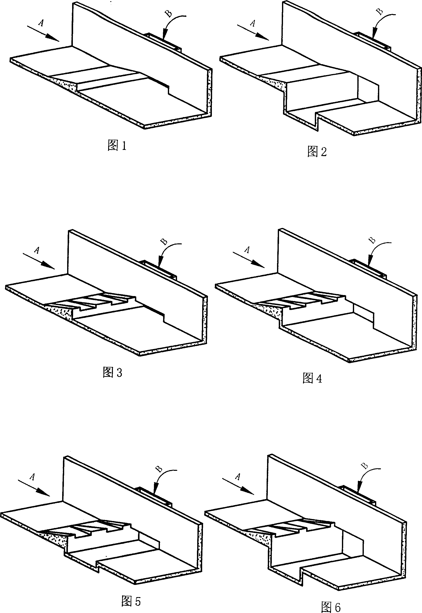
Differential aeration sluice device

A differential type, sill-reeling technology, applied in the field of aerated sills, can solve problems such as aggravating water surface fluctuations, worsening downstream water flow patterns, increasing engineering volume, etc., reducing engineering costs, simple and easy structure, and extending protection length. Effect

Inactive Publication Date: 2007-12-19
HOHAI UNIV +1
View PDF0 Cites 13 Cited by
  • Summary
  • Abstract
  • Description
  • Claims
  • Application Information

AI Technical Summary

Problems solved by technology

Tests have proved that: under the condition of large single-width flow, excessively increasing the height of the sill and the bottom slope of the sill will aggravate the fluctuation of the water surface and deteriorate the flow state of the downstream water. For the Changming Flow Cave, the safety margin of the cave body will be reduced It is necessary to increase the height of the hole body and increase the amount of engineering

Method used


Image

  • Differential aeration sluice device
  • Differential aeration sluice device
  • Differential aeration sluice device

Examples


Embodiment 1

[0043] The effectiveness of the invention is verified by using several different aeration types of a 1:30 scale model of a certain project.

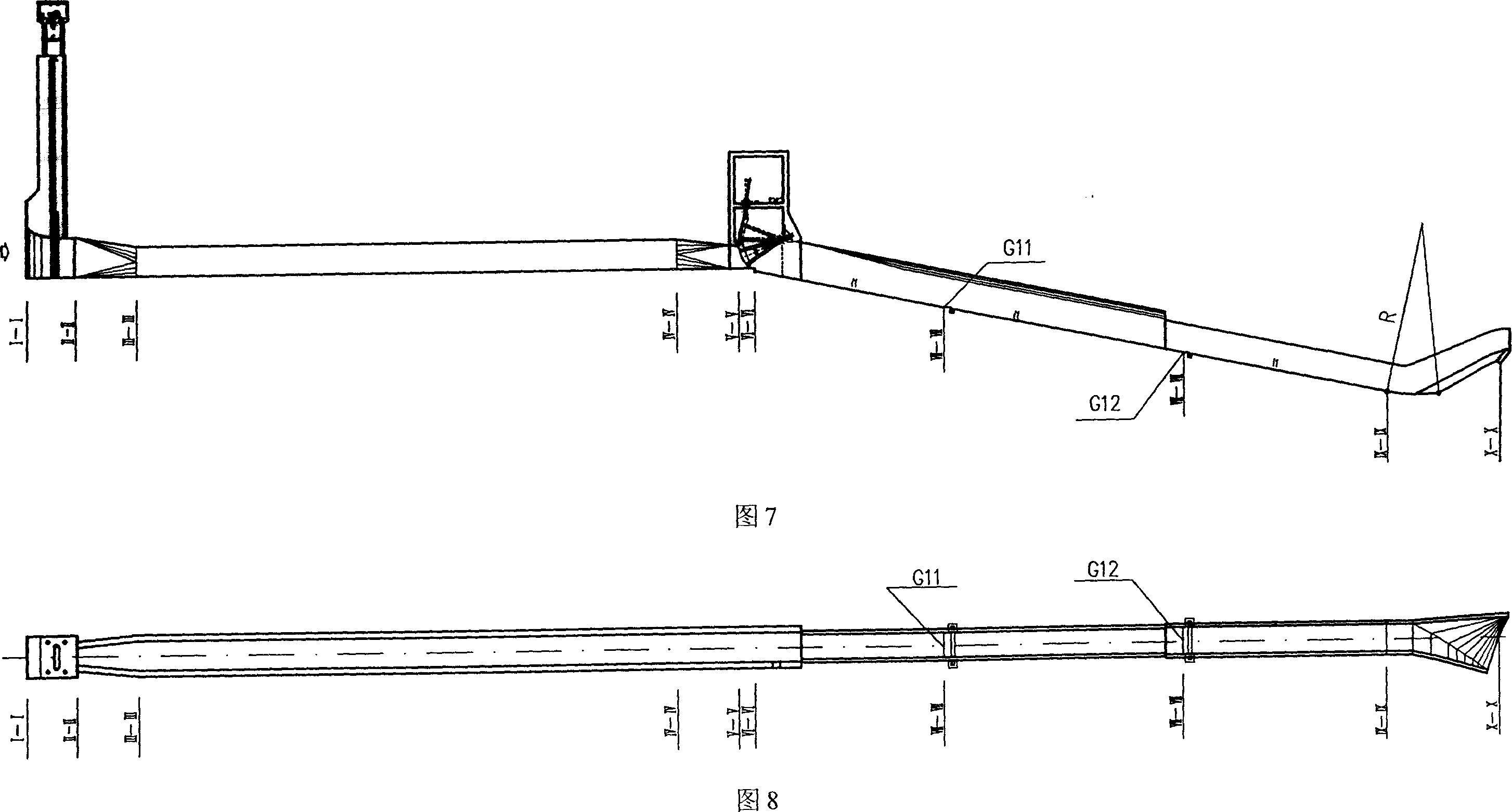
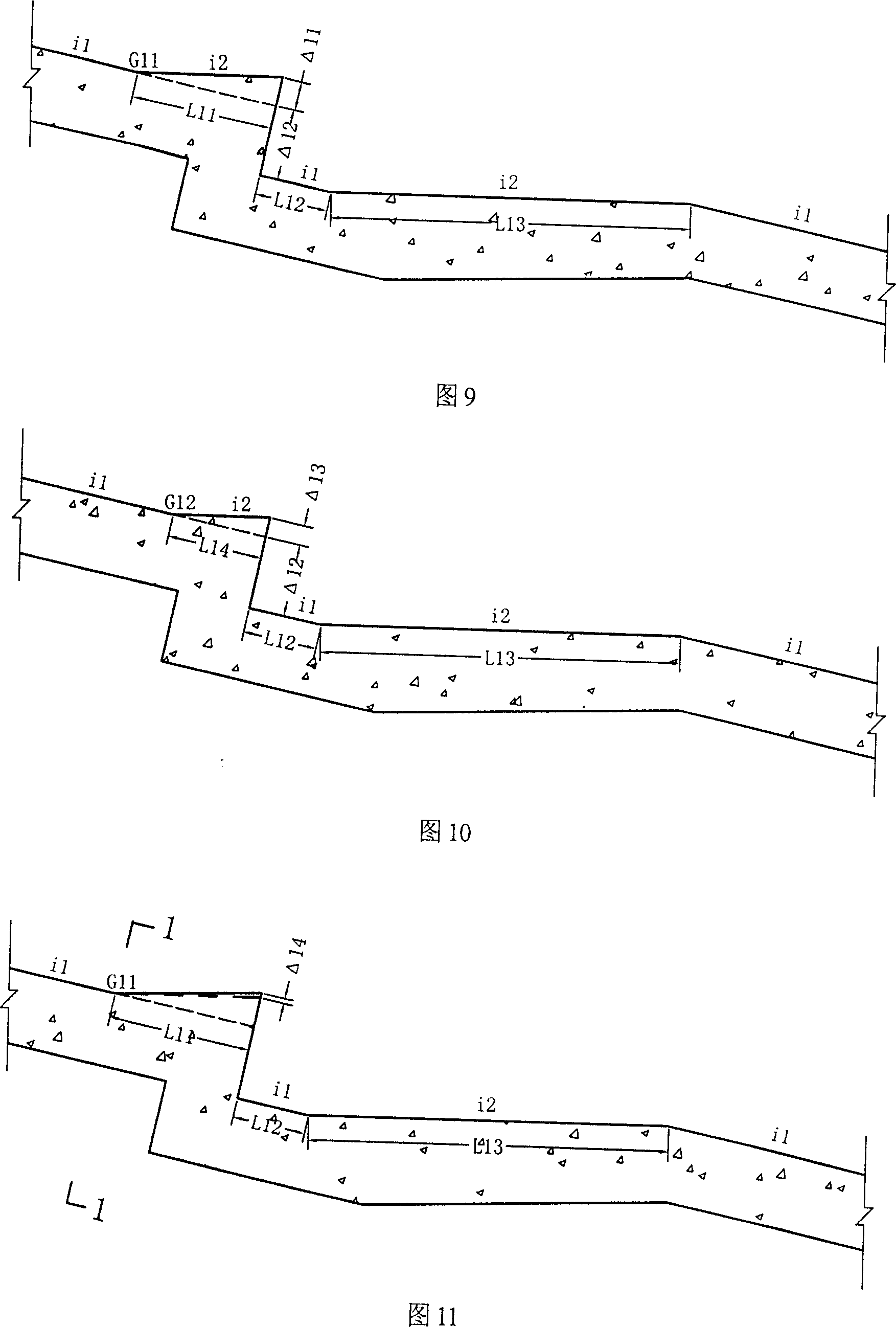
[0044] Under the same test conditions, only the shape of the ridge in the upstream and downstream aeration facilities is changed, and the prototype dimensions corresponding to each scheme are shown in Figure 7-14.

[0045] As shown in Figure 7 and Figure 8, the front section of the spillway tunnel is a 287.6m long horizontal section with pressure, and a drop sill (0+291.10m) is set behind the exit arc door, and the bottom slope (i1) of the spillway tunnel behind the drop sill is 0.2063, add two aeration facilities combining ridges and aeration tanks at stake number 0+374.63m (upstream ridge starting point G11) and 0+472.02m (downstream ridge starting point G12). At the outlet section of the spillway, from the pile number 0+555.88m, the bottom slope becomes arc-shaped (arc radius R=70m), and the rear part is a twisted nose sill outflow. ...


PUM


Abstract

The present invention relates to a kind of differential-type aerated deflecting bucket. It includes bucket body, and its characterized by that on the bucket body locally are set several small deflecting buckets, these small cleflecting buckets and said bucket body are identical in the slope-raising point, and the overflowing surfaces fromed from these small deflecting buckets and said bucket body are convexly-concavely alternated. Said invention also provides the working principle of said differential-type aerated deflecting bucket. Said deflecting bucket can effectively raise amount of air entrainment and can effectively protect outlet structure against cavitation erosion.

Description

technical field [0001] The invention relates to an air-entraining ridge mainly used for drainage structures in water conservancy projects, in particular to a differential air-entraining ridge. technical background [0002] In the construction of high dams, the investment in drainage structures accounts for about 40-60% of the entire project. When the water head reaches or exceeds 100m, its flow velocity will reach or exceed 35m / s, and the resulting hydraulic problems are all high-speed water flow problems, which pose a serious threat to the safe operation of the project. Among them, the problem of cavitation and cavitation is the most prominent, which directly affects the safe operation of buildings. [0003] Numerous experiments and engineering practices have proved that the occurrence of cavitation erosion can be effectively prevented and alleviated by aerating the water flow, thereby protecting the water boundary from damage caused by cavitation erosion. And to make the...

Claims


Application Information

Patent Timeline
IPC IPC(8): E02B8/06E02B3/10
Inventor 吴建华阮仕平吴伟伟纽新强廖仁强胡中平向光红
Owner HOHAI UNIV
Learn More