
Storage cage

A storage cage and base technology, applied in the field of storage cages, can solve the problems of more stringent process requirements, collapse, and inability to stack

Inactive Publication Date: 2007-12-19
SUZHOU PINGFANG IND CO LTD
View PDF2 Cites 1 Cited by
  • Summary
  • Abstract
  • Description
  • Claims
  • Application Information

AI Technical Summary

Problems solved by technology

[0002] The storage cages in the prior art have corresponding deficiencies whether they are filled with goods or in an empty cage state. When they are full of goods, they cannot be stacked reliably, resulting in a large space occupation. Even if they are barely stacked, However, due to the lack of good control between each other, the height of the stack is limited, otherwise it will cause collapse, damage the goods or bury it and cause hidden dangers to personal safety; in the empty cage state, because it is not foldable, it also causes occupancy. The space is large, which increases the transportation cost for the turnover
[0003] Chinese Patent Authorization Announcement No. CN2683542Y discloses a foldable cargo turnover box. The achievement of this scheme is that the four sides of the box, that is, the four walls of the box, can be folded onto the bottom of the box, no matter for the manufacturer of the turnover box product or for the user It can be reduced in size when empty, saving transportation costs and occupying storage space, but it is a disadvantage that it cannot be stacked when it is full
[0004] Chinese patent authorization announcement number CN2505414Y teaches a foldable turnover box. This technical solution can be folded and stacked, so it solves the problem that the previous patent cannot be stacked. However, the applicant finds that this turnover box still exists. The deficiencies are as follows: one is that four angle irons are used as the base frame (the patent is called the base), and then the bottom net plate is welded on the bottom frame, between the rear edge of the bottom net plate and the lower edge of the rear net plate, and the two sides of the rear net plate It is hinged together with the rear edge of the corresponding side screen panels by means of spiral hinges and iron splints (see lines 13-22 on page 2 of the instruction manual), so although the front, rear, left and right screen panels can be folded, the Since the defects of the spiral hinge are well known, the longer it is, the easier it is to deform, resulting in ineffective folding. In addition, the deformation of the screen can easily lead to the deformation of the hinge, so the durability of the spiral hinge is very fragile. Once a certain hinge fails , which will cause the entire turnover box to be unable to be folded; second, the lengthy helical hinge has great resistance in the process of folding or unfolding the mesh panel, and has poor flexibility, especially when debris invades and can easily get stuck 3. In order to reflect the stackability, the patent is at the lower end of the underframe, more specifically at the four corners of the underframe respectively welding a foot, and the lower ends of each foot form an inverted U-shaped groove. The angle between the bottom of the tank and the outer wall of the tank is 95-105°, so the processing requirements are relatively strict. In addition, it is difficult to set the upper part of the turnover box to be compatible with the inverted U-shaped groove of another turnover box. Fourth, in terms of the overall structure of the turnover box, the stacking height is very limited, and it is very prone to the risk of automatic collapse without touching
[0005] In addition, there is also a common deficiency in the above two patented technologies, that is, it is difficult to attach labels with information such as product name, model, specification, production date, quantity (including dynamic decrement) on the turnover box

Method used


Image

  • Storage cage
  • Storage cage

Examples


Embodiment Construction

[0020] Through the applicant's detailed description below, it will be more helpful to understand the concept of the present invention, and make the advantages and positive effects of the present invention clearer. However, the description of the embodiments does not constitute a limitation of the present invention. A slight change in form or an equivalent substitution or a literal modification should be considered as belonging to the scope of the technical solutions disclosed in the present invention.

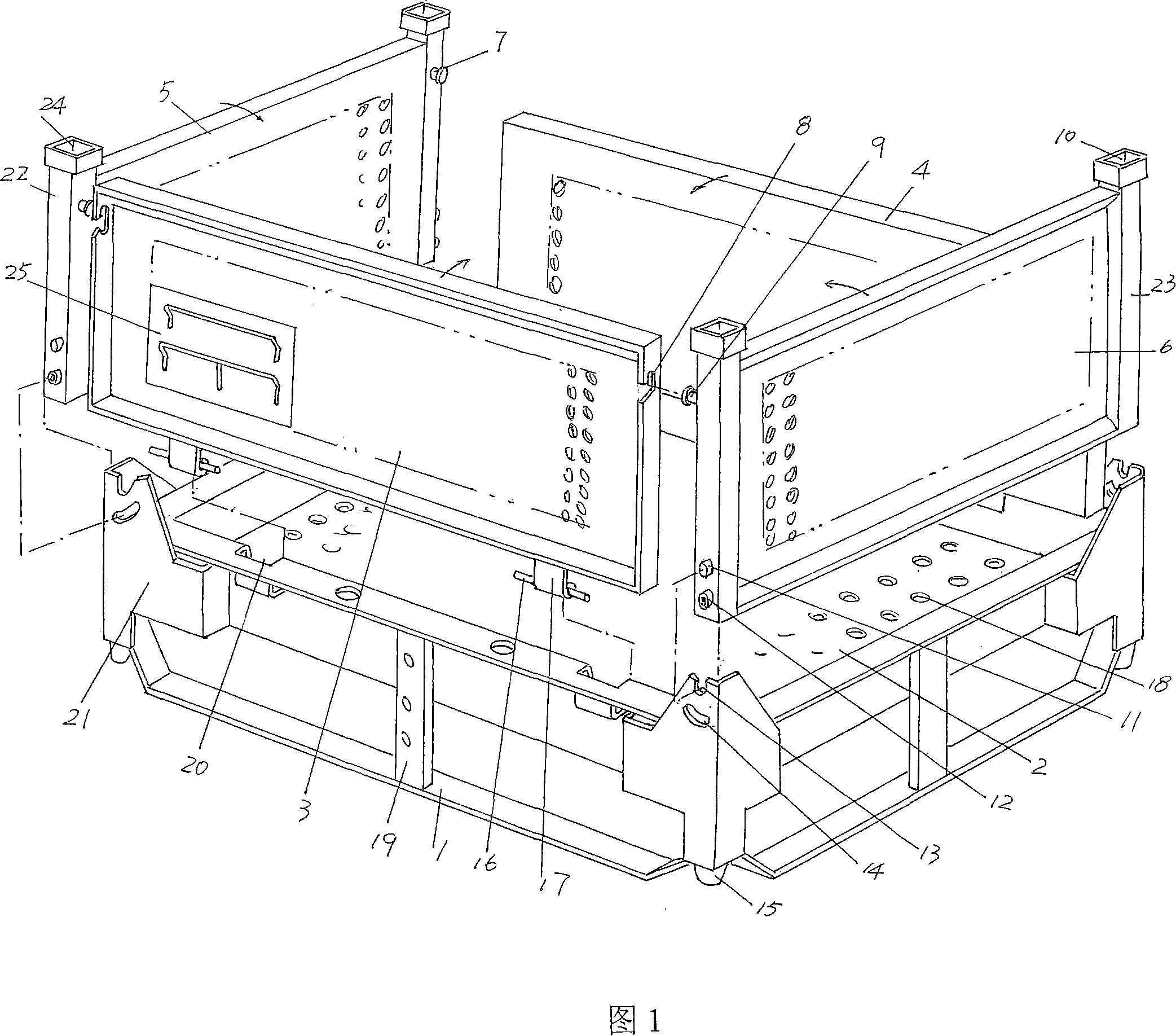
[0021] Referring to Fig. 1, a rectangular base 1 is provided so as to form four right angles, each of the four right angles of the base 1 is provided with a base angle foot 21, and there are mainly two situations for the package described here, One is that when the base 1 is made of plastic, the corner feet 21 of the base are formed in the form of material reinforcement while molding; the other is that when the base 2 is made of metal material, the corner feet 21 of the base are...


PUM


Abstract

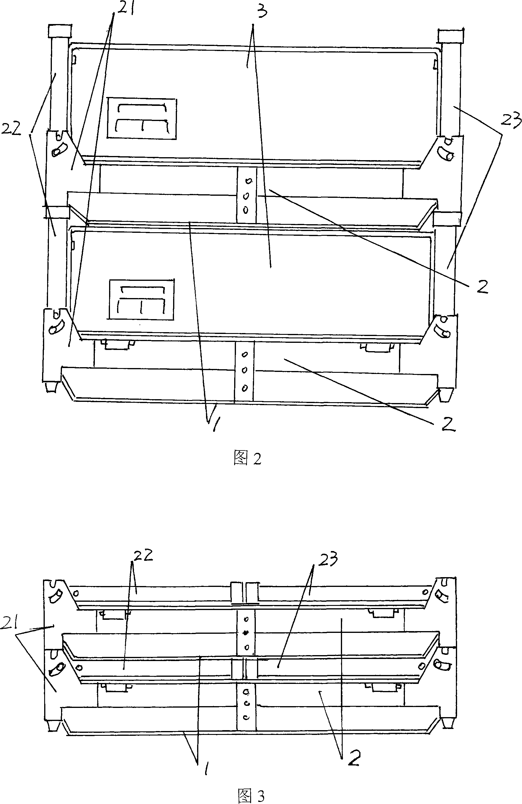
The storage cage as one turnover cargo transporting article includes pedestals, base plates, and four side plates to form the side walls. Each of the pedestals has corner feet with tenon in the lower part and pin shaft slot and pin shaft hole in the upper part, and hinge cavity; each of the front and the back side plate has hinge and connecting pin slot; and each of the right and left side plate has one pair of uprights with grooves and pins for connecting the front and the back side plate in the upper part and pin shaft in the lower part. The storage cage may have the side plates folded onto the pedestals to save space.

Description

technical field [0001] The invention relates to a storage cage, which is used in industries such as industrial and mining enterprises, shopping malls, supermarkets, and logistics industries as a turnover appliance for storing and transporting goods. Background technique [0002] The storage cages in the prior art have corresponding deficiencies whether they are filled with goods or in an empty cage state. When they are full of goods, they cannot be stacked reliably, resulting in a large space occupation. Even if they are barely stacked, However, due to the lack of good control between each other, the height of the stack is limited, otherwise it will cause collapse, damage the goods or bury it and cause hidden dangers to personal safety; in the empty cage state, because it is not foldable, it also causes occupancy. The space is large, which increases the transportation cost for the turnover. [0003] Chinese Patent Authorization Announcement No. CN2683542Y discloses a foldab...

Claims


Application Information

Patent Timeline
IPC IPC(8): B65D6/18B65D21/032B65D19/02B65D19/38
Inventor 平雪明
Owner SUZHOU PINGFANG IND CO LTD
Learn More