
Manipulator paw based on stepping motor

A technology of stepping motors and manipulators, applied in the field of intelligence, can solve problems such as expensive prices and complex structures

Inactive Publication Date: 2007-12-12
于复生
View PDF0 Cites 26 Cited by
  • Summary
  • Abstract
  • Description
  • Claims
  • Application Information

AI Technical Summary

Problems solved by technology

However, the mechanical claws currently on the market have complex structures and are more expensive.

Method used


Image

  • Manipulator paw based on stepping motor

Examples


Embodiment

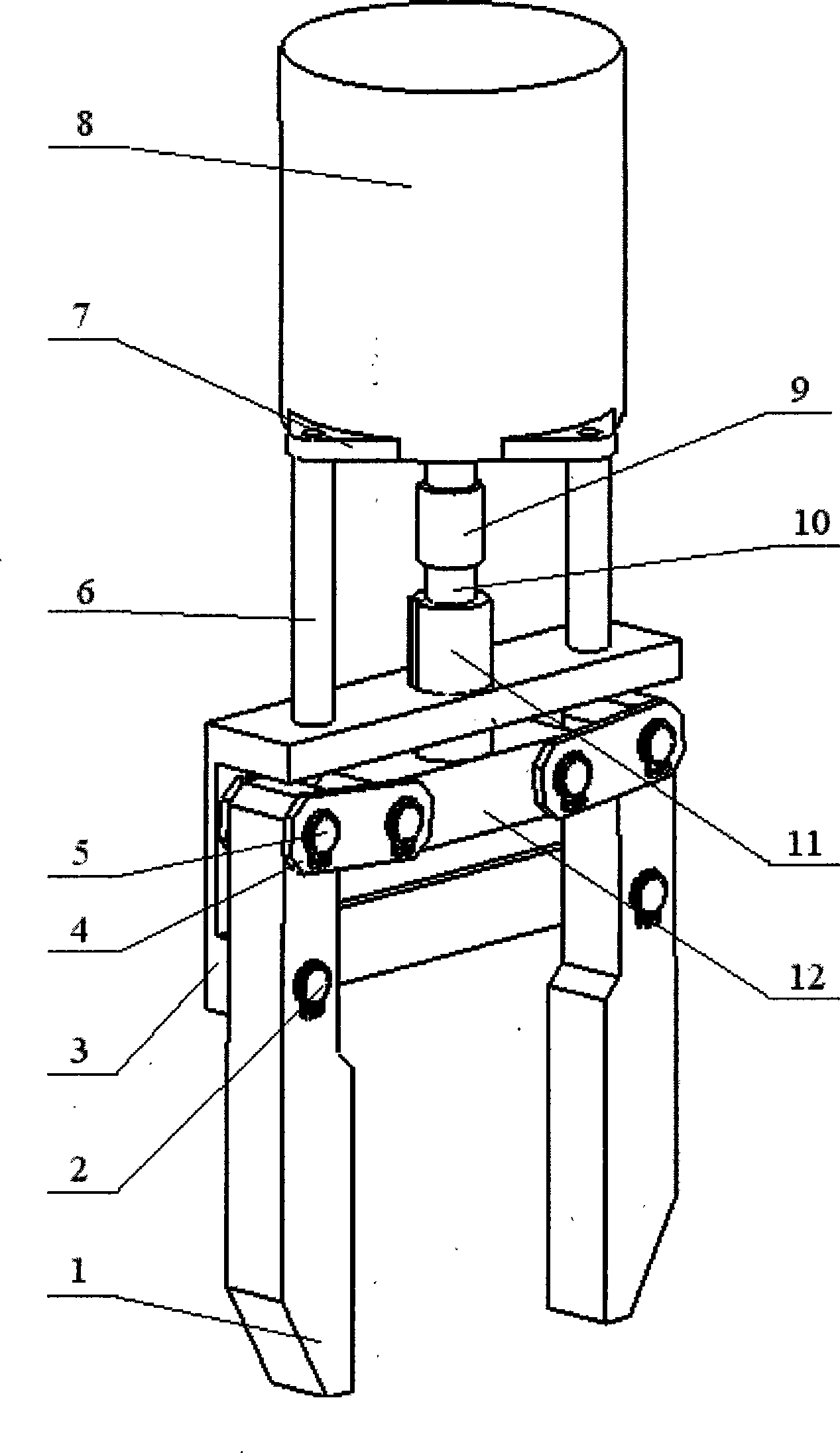
[0014] Embodiment: In the accompanying drawings, the stepper motor 8 is connected to the finger base plate 3 through the motor connection sleeve 6, the gripper device is hinged on the finger base plate 3, and the stepper motor 6 is connected to the gripper device through a lead screw 10. The claw device includes a claw push plate 12, a finger bottom plate 3, a connecting plate 4, a finger 1 and a finger shaft, the upper end of the finger 1 is hinged with the claw push plate 12 through the connecting plate 4 and the finger shaft A5, and the finger 1 is symmetrically located on Claw push plate 12 both sides. The claw push plate 12 is connected with the lead screw 10, and the middle part of the finger 1 is hinged with the finger bottom plate 3 through the finger shaft B2.

[0015] The output end of the stepping motor 8 is provided with a stepping motor fixing plate 7, one end of the motor connection sleeve 6 is fixed on the stepping motor fixing plate 7, and the other end is fixe...


PUM


Abstract

The invention relates to the mechanical robot grip. It comprises the motor, connection sleeve, finger bottom plate and grip device, with the motor connected to the finger bottom plate through the linking sleeve barrel, grip hinged to the finger bottom plate, motor connected to the grip through the screw rod. When the progressive motor rotates clockwise viewing from its back, it drives the clockwise rotation of the screw rod through the coupler. Due to the right rotation model of the screw rod mother screw, it can restrain the freedom of the rotation direction, with the mother screw moving downward, driving the downward movement of the grip push plate, driving the open of the fingers, and vice versa. It is simple, low in cost, small in size, and flexible.

Description

technical field [0001] The invention relates to a field of intelligent technology, a manipulator gripper based on a stepping motor, specifically a manipulator gripper that always uses a stepping motor to drive a variable crank-slider mechanism to drive the movement of the gripper. Background technique [0002] Manipulator is a high-tech automatic production equipment developed in recent decades. Manipulator is an important branch of robot. Its feature is that it can be programmed to complete various expected tasks, and it combines the advantages of both humans and machines in terms of structure and performance, especially reflecting the intelligence and adaptability of humans. The manipulator claw is the key part of the manipulator, and its flexibility and accuracy determine the manipulator's flexibility and accuracy to a large extent. Therefore, it is imperative to design a robotic gripper with small size, good flexibility and high accuracy. However, the mechanical claws...

Claims


Application Information

Patent Timeline
Patent Type & Authority Applications(China)
IPC IPC(8): B25J15/00
Inventor 于复生沈孝芹李琦郭梅静李巍张玉清
Owner 于复生
Learn More