
Liquid controlled reversing buffering mechanism and method

A technology of hydraulically controlled reversing and buffering devices, which is applied in fluid pressure actuators, pump control, liquid variable capacity machinery, etc., and can solve the problems of poor position detection accuracy and stability, poor control stability, and affecting the effect of buffer control, etc. problem, to achieve the effect of improving position detection accuracy, good adaptability, and good stability

Inactive Publication Date: 2007-12-05
CHINA INTERNATIONAL MARINE CONTAINERS (GROUP) CO LTD +1
View PDF0 Cites 9 Cited by
  • Summary
  • Abstract
  • Description
  • Claims
  • Application Information

AI Technical Summary

Problems solved by technology

The measurement of oil pressure between positions is easily affected by the performance and response time of the differential pressure sensor, resulting in poor position detection accuracy and stability and affecting the effect of buffer control
In addition, in order to adapt to the oil pressure changes caused by differential pressure sensors with different performances and other factors, such as machining accuracy, it is necessary to frequently modify the parameters of the displacement control curve of the main oil pump, resulting in the parameter setting of the reversing buffer device. Complicated and poor control stability

Method used


Image

  • Liquid controlled reversing buffering mechanism and method
  • Liquid controlled reversing buffering mechanism and method
  • Liquid controlled reversing buffering mechanism and method

Examples


Embodiment Construction

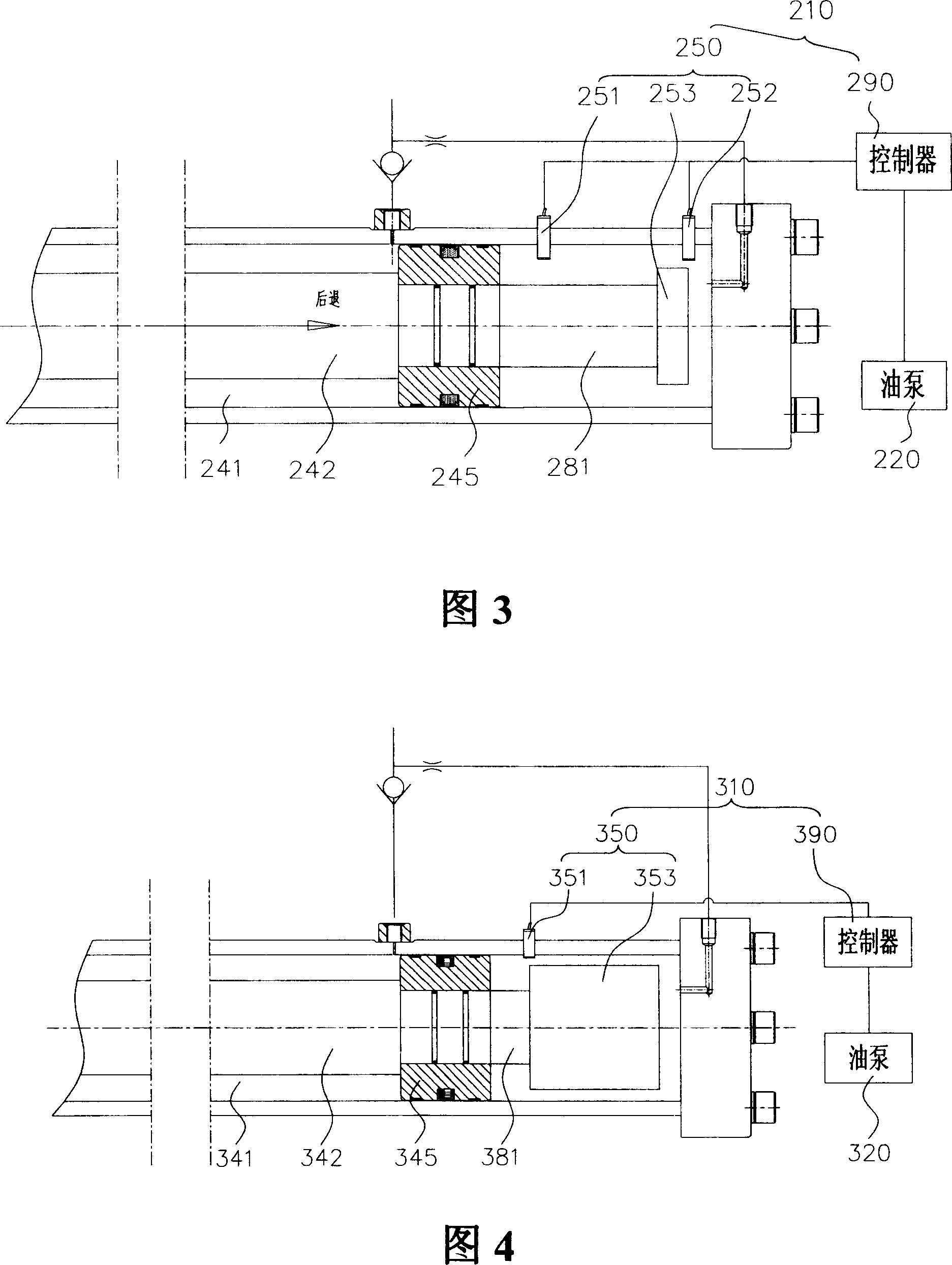
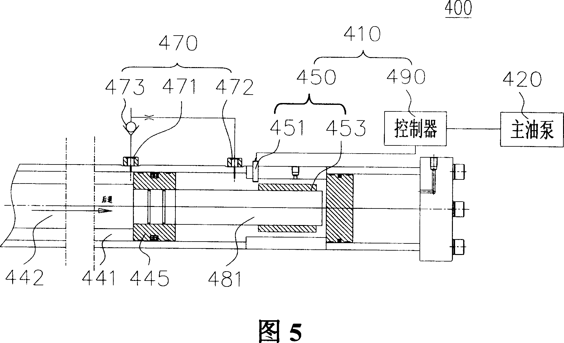
[0020] FIG. 3 shows a reversing buffer device 210 according to a preferred embodiment of the present invention, which includes a position detection device 250 and a controller 290 . The position detection device 250 further includes two position sensors 251 and 252 and an induction block 253 arranged axially on the cavity wall of the oil cylinder 241 . The two position sensors 251 and 252 are separated by a predetermined distance, such as 100mm-200mm, and the position sensor 252 is located near the end of the oil cylinder 241 . One end of the piston 245 is connected with the piston rod 242, and the other end is connected with the induction block 253 through the connecting rod 281. The induction block 253 is preferably a cylinder and has a relatively small thickness, such as 20mm-40mm, and can be connected with the piston. 245 moves together. Wherein, the length of the connecting rod 281 corresponds to the distance between the sensors 251 and 252 .

[0021] As shown in the fi...


PUM


Abstract

The invention discloses a liquid control reversing buffer device and method. The device includes position detection device which used in detecting piston moving location of liquid control reversing system and produce position signal. Controller is used in receiving position signal and accord to the signal to regulate oil pump displacement of liquid control reversing system, and then realize the buffer to piston reversing. The device can direct measure position of piston, then improve signal detection precision and dynamic responsiveness, and make liquid control reversing system stable.

Description

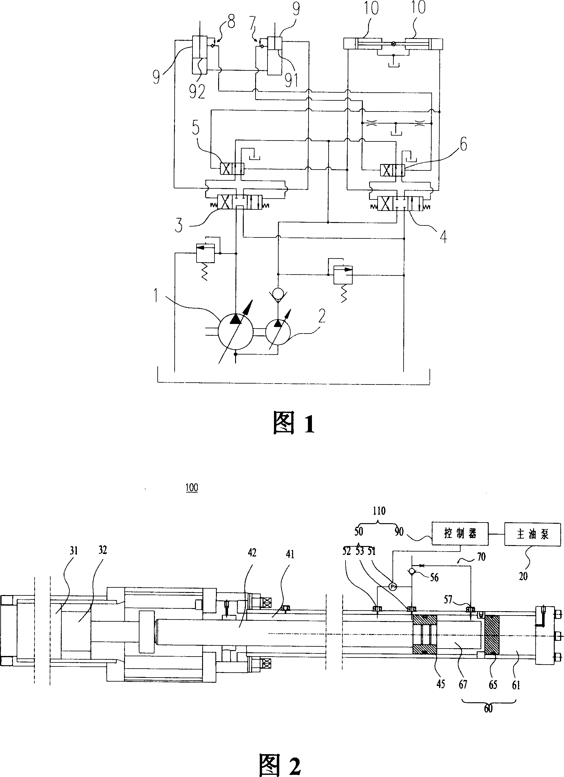
technical field [0001] The invention relates to a reversing buffer device and method, in particular to a reversing buffer device and method used in concrete delivery pumps, which can reduce the impact and vibration on the equipment during pumping reversing. Background technique [0002] There are two types of hydraulic systems in concrete conveying equipment: open and closed. For the open system, when the hydraulic control is used for reversing, the concrete piston will hit its bottom and produce a large impact vibration, which will easily cause fatigue damage to the structural parts of the equipment, increase the swing of the pump truck arm, and make noise. Therefore, buffer measures must be taken for hydraulic systems with hydraulically controlled reversing systems. [0003] The working principle of the hydraulic control reversing system is shown in Figure 1, in which the main oil pump 1 is a proportional variable pump with adjustable displacement, which drives a pair of ...

Claims


Application Information

Patent Timeline
Patent Type & Authority Applications(China)
IPC IPC(8): F15B21/02F04B49/00E04G21/02
Inventor 谢恒星
Owner CHINA INTERNATIONAL MARINE CONTAINERS (GROUP) CO LTD
Learn More