Communication antenna and pole with built-in-antenna

A technology for communication antennas and antennas, applied to antennas, individually powered antenna arrays, antenna supports/mounting devices, etc., which can solve the problems of lack of antennas, increase in the cost of communication antennas, and the inability to fully ensure installation space, etc.

Inactive Publication Date: 2007-11-28
ORMON CORP
View PDF3 Cites 6 Cited by
  • Summary
  • Abstract
  • Description
  • Claims
  • Application Information

AI Technical Summary

Problems solved by technology

[0005] However, according to the above-mentioned existing method of installing a plurality of communication antennas, in addition to the cost increase due to the increase in the number of communication antennas, it is also necessary to ensure the installation space corresponding to the plurality of antennas. When the above-mentioned installation space cannot be sufficiently ensured, the number of antennas is insufficient. Unavoidable generation of RFID tags that cannot communicate, and there is a problem that it cannot be used in a large area
[0006] In addition, according to the above-mentioned conventional method of moving a communication antenna, it is necessary to move the unit of the communication antenna. In addition to causing an increase in cost, it is also necessary to ensure the movement path of the communication antenna. If the above-mentioned movement path cannot be ensured, the mobile communication cannot be physically performed. In the case of an antenna, many RFID tags that cannot communicate are generated, and there is a problem that it cannot be used in a large area

Method used


Image

  • Communication antenna and pole with built-in-antenna
  • Communication antenna and pole with built-in-antenna
  • Communication antenna and pole with built-in-antenna

Examples


Embodiment Construction

[0042] Hereinafter, preferred embodiments of the present invention will be described in detail with reference to the drawings.

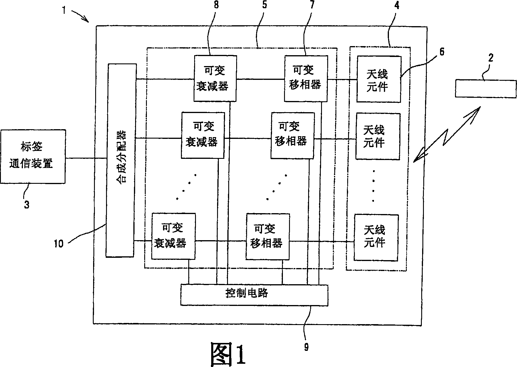
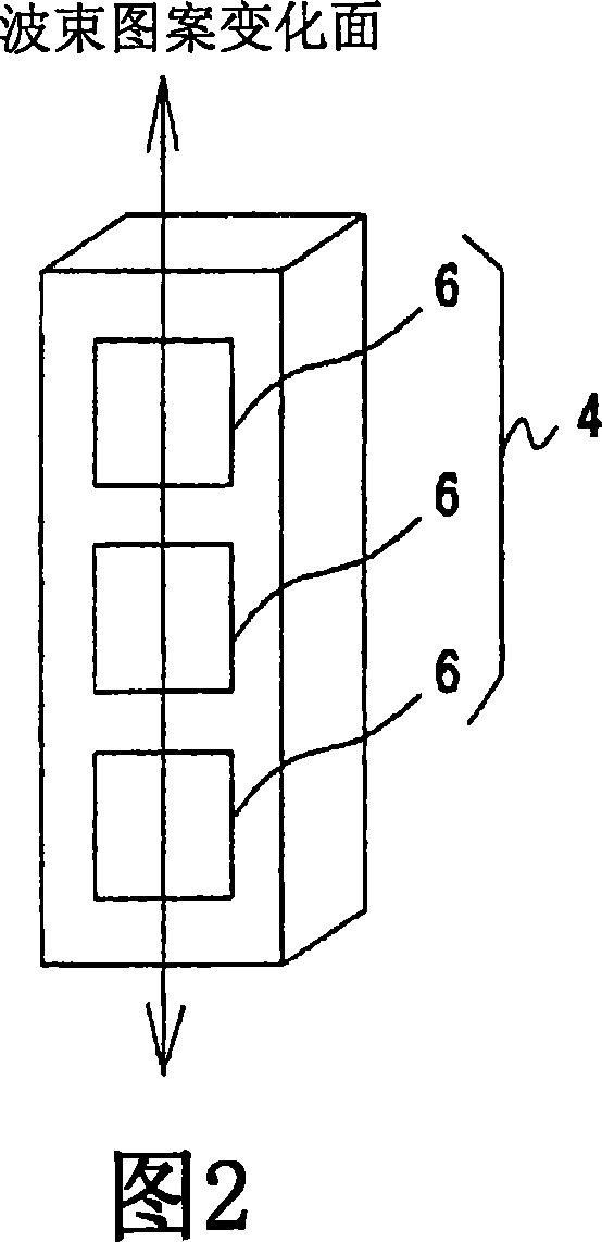
[0043] FIG. 1 is a block diagram of a communication antenna to which the present invention is applied. This communication antenna 1 is an antenna used in a tag communication device 3 such as an RFID reader / writer that wirelessly communicates with an RFID tag 2 via radio waves. The communication antenna 1 includes an antenna array. part 4 and variable unit 5, and the antenna array part 4 has a plurality of antenna elements 6. In addition, an arrangement structure of the plurality of antenna elements 6 will be described later.

[0044] A variable phase shifter 7 and a variable attenuator 8 constituting the above-mentioned variable unit 5 are respectively connected to each antenna element 6 , and the variable phase shifter 7 and variable attenuator 8 are connected to a control circuit 9 . The control circuit 9 changes the phase of the high-frequency si...


PUM


Abstract

An antenna array part constituting a communication antenna is composed of a plurality of antenna elements. The antenna elements are arranged on an arc. This allows radio waves to be irradiated also in the exact transverse direction of the antenna array part, thereby making available the communications with an RFID tag positioned in the exact transverse direction. By shifting the phase of a radio frequency signal supplied to each antenna element or adjusting the amplitude of the radio frequency signal, it is possible to change the direction of radio beams irradiated from the antenna array part or expand the width of the radio beams thus making available with RFID tags present in a wider area.

Description

technical field [0001] The present invention relates to a communication antenna used in a tag communication device such as an RFID reader-writer, and an antenna built-in rod incorporating the communication antenna. Background technique [0002] Since the communication antenna used for the RFID reader / writer is mounted on a wall or the like, a planar antenna is generally preferable. This is because, for example, when the communication antenna is installed on both sides of the transport device in the factory, the goods on the transport device will collide with the communication antenna. In addition, when the communication antenna is installed on the dockway at the time of shipment, the truck etc. will collide with the communication antenna. [0003] Patch antennas are often used as such planar antennas. The radio beam width radiated from the patch antenna is about 60°, so it is difficult for radio waves to reach an area wider than 60°, and it is difficult to communicate with...

Claims


Application Information

Patent Timeline
Patent Type & Authority Applications(China)
IPC IPC(8): H01Q21/00H01Q1/22H01Q3/26G06K19/07H04B5/02
CPCH01Q1/2216H01Q3/26H01Q21/20
Inventor 安藤浩次河合武宏
Owner ORMON CORP
Why Eureka
Try Eureka