Eureka AIR delivers breakthrough ideas for toughest innovation challenges, trusted by R&D personnel around the world.

Light-emitting apparatus

A light-emitting device and phosphor technology, applied in fluorescent screen lamps, discharge tube cold cathodes, discharge lamps, etc., can solve the problems of good luminous efficiency and achieve the effect of improving luminous efficiency and reducing radiation

Inactive Publication Date: 2007-11-14
SUBARU CORP
View PDF1 Cites 24 Cited by
  • Summary
  • Abstract
  • Description
  • Claims
  • Application Information

AI Technical Summary

Problems solved by technology

In such a light-emitting device, the light emitted from the surface of the phosphor layer is usually radiated to the outside through the glass substrate behind the phosphor layer. However, it cannot be said that the luminous efficiency of the device is good because the luminescence becomes useless luminescence and is radiated into the vacuum vessel.

Method used


Image

  • Light-emitting apparatus
  • Light-emitting apparatus
  • Light-emitting apparatus

Examples


Embodiment Construction

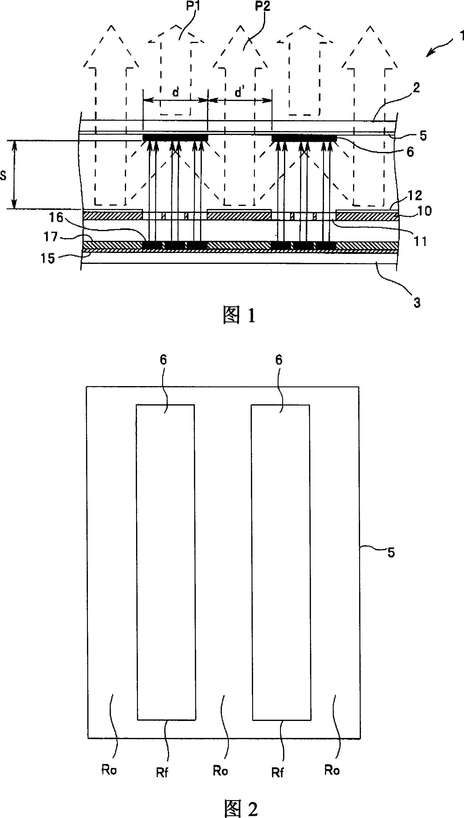
[0017] Hereinafter, embodiments of the present invention will be described with reference to the drawings. 1 to 4 are related to the first embodiment of the present invention. FIG. 1 is a basic configuration diagram of a light emitting device, FIG. 2 is a plan view showing the arrangement of phosphors, and FIG. 3 is a plan view showing the arrangement of a reflection surface of a gate electrode. 4 is a plan view showing the configuration of the cold cathode electron emission source.

[0018] In FIG. 1, reference numeral 1 is a light-emitting device, which is used, for example, as a planar electric field emission type illuminating lamp. The light-emitting device 1 has the following basic structure: a glass substrate 2 on the light-emitting surface side and a glass substrate 3 on the base surface side are arranged opposite to each other at a predetermined interval to form a vacuum container that maintains a vacuum inside. The anode electrode 5, the gate electrode 10, and the cathode...


PUM


Abstract

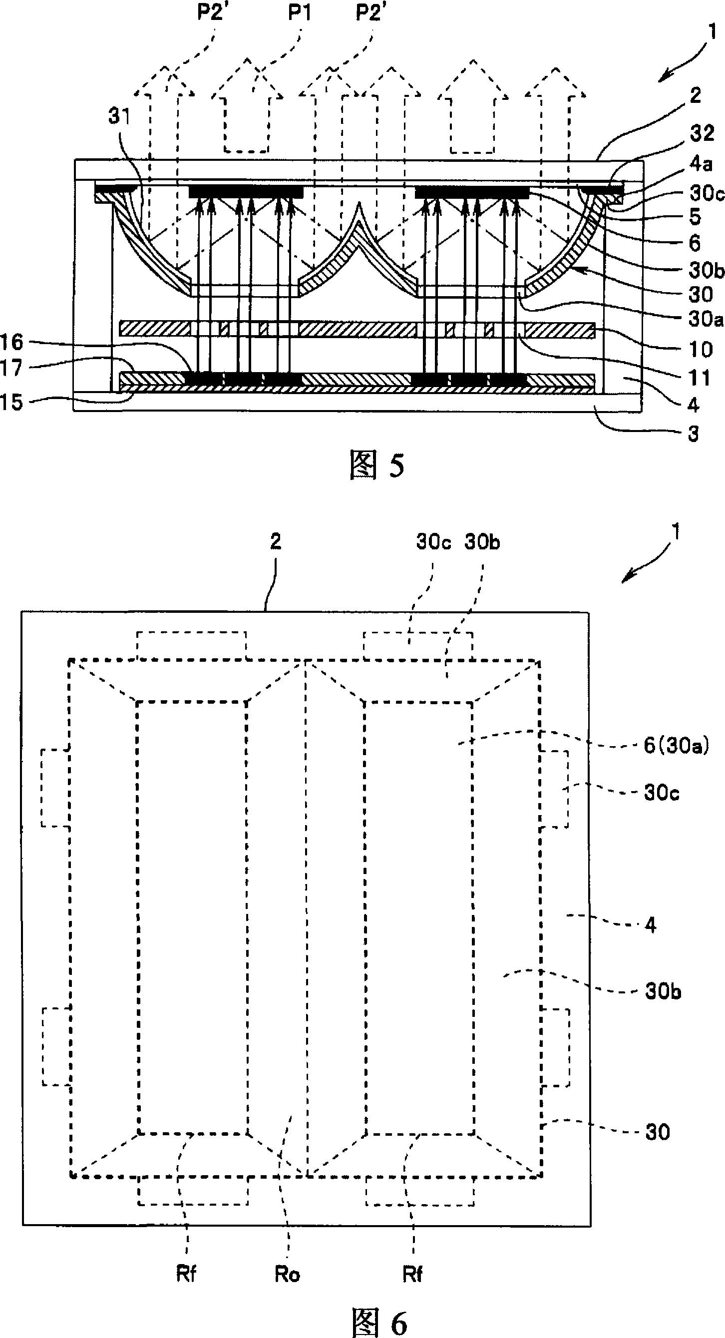
A light-emitting apparatus of the present invention maintains an anode electrode 5 at a higher positive electric potential than a cathode electrode 15, applies an electric field to a cold-cathode electron emission source 16 by controlling a gate voltage applied to the cathode electrode 15 with a gate electrode 10, and emits excitation light from a phosphor 6 irradiated by an electron beam released from the cold-cathode electron emission source 16. The light-emitting apparatus of this invention emits the excitation light not only from the opposite side of the electron beam-irradiated surface of the phosphor 6 through a glass substrate 2, but also from the electron beam-irradiated surface of the phosphor 6 by reflecting the excitation light with a gate reflection surface 12 on the gate electrode 10 and emitting it through an unobstructed area Ro of the glass substrate 2. This eliminates the wasted excitation light emitted and absorbed within the apparatus as in the conventional light-emitting apparatuses to thereby improve the luminous efficiency and substantially increase the amount of light emitted outside from the entire illumination surface.

Description

Technical field [0001] The present invention relates to a light-emitting device, which uses electrons emitted from a cold cathode electron emission source electric field to excite phosphors to emit light. Background technique [0002] In recent years, compared to existing light-emitting devices such as incandescent lamps or fluorescent lamps, electron beam excitation type light-emitting devices have been developed. The electrons emitted from the electric field of the electron emission source collide with the fluorescent body at a high speed in a vacuum container to cause fluorescence. Body excitation light, used for lighting or image display. In this type of light-emitting device, it is usually a structure in which the light from the surface of the phosphor layer passes through the glass substrate on the inner side of the phosphor layer and radiates to the outside. However, in this structure, the surface of the phosphor irradiated by the electron beam is the strongest The ground ...

Claims


Application Information

Patent Timeline
Patent Type & Authority Applications(China)
IPC IPC(8): H01J31/12H01J29/02
CPCH01J63/06H01J61/025H01J61/305H01J1/30H01J31/12H01J29/28
Inventor 高桥久也难波笃史
Owner SUBARU CORP
Why Eureka
Eureka Blog
Learn More