
Device for upsetting and crimping

A curling and driving device technology, applied in the field of stuffing and curling devices

Inactive Publication Date: 2007-11-07
SAURER GMBH & CO KG
View PDF1 Cites 0 Cited by
  • Summary
  • Abstract
  • Description
  • Claims
  • Application Information

AI Technical Summary

Problems solved by technology

But this requires an additional mechanical structure, which increases the risk of transmission errors

Method used


Image

  • Device for upsetting and crimping
  • Device for upsetting and crimping
  • Device for upsetting and crimping

Examples


Embodiment Construction

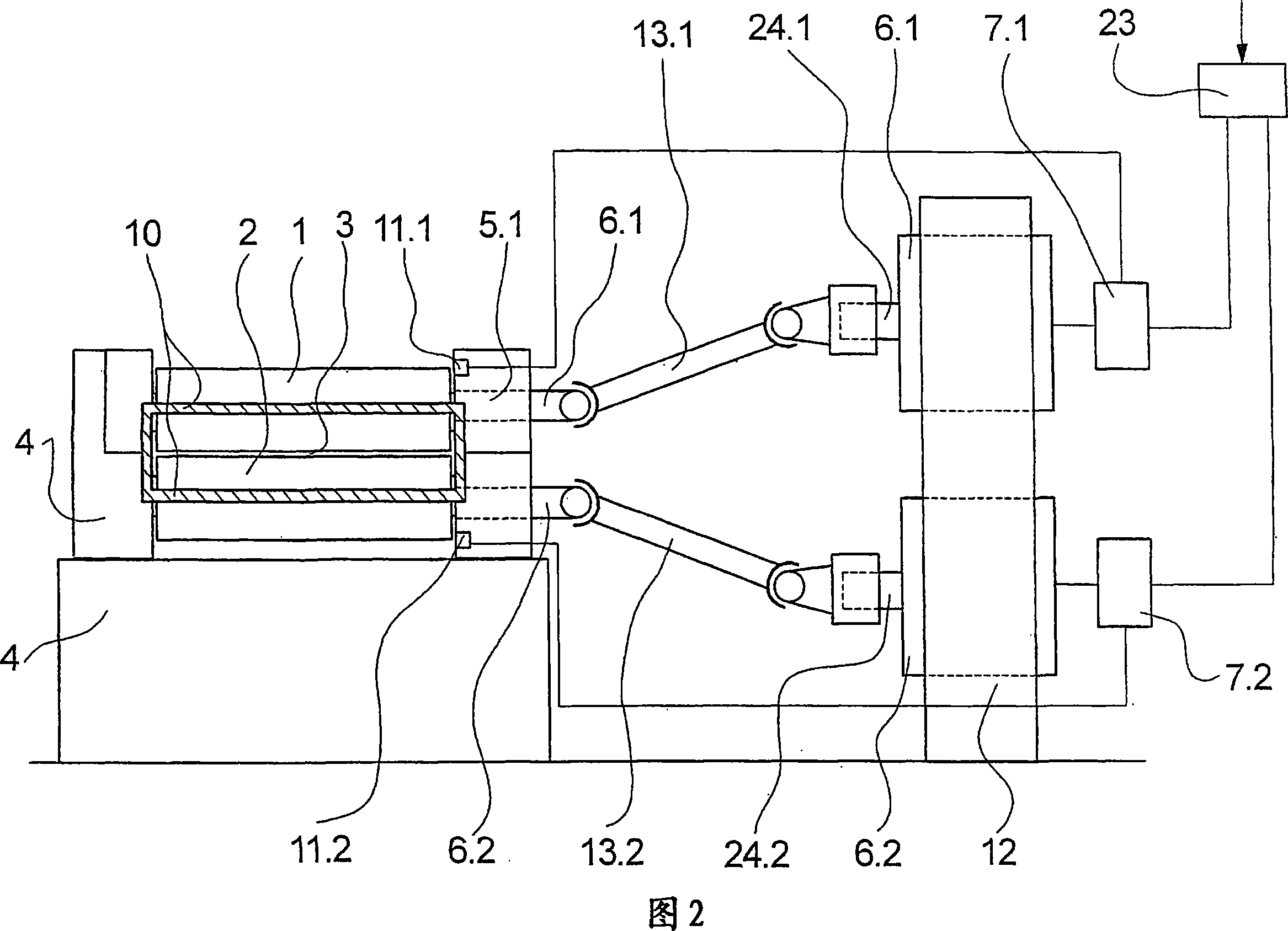
[0024] FIG. 1 shows schematically a first exemplary embodiment of the device according to the invention in a view.

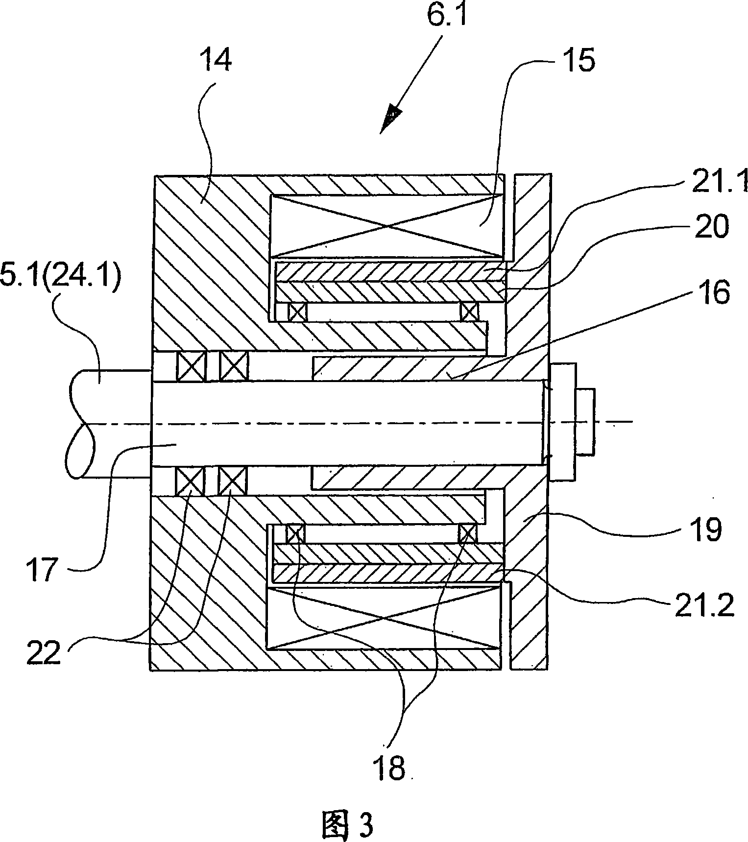
[0025] The device for stuffing and crimping synthetic fibers essentially comprises two rolls 1 and 2 mounted rotatably in a machine frame 4 and a stuffing box 10 arranged downstream of the rolls 1 and 2 . FIG. 1 shows a stuffer box 10 connected downstream of the rollers 1 and 2 in a transverse section. A roll gap 3 is formed between the upper roll 1 and the lower roll 2 to enable the fiber product to be pulled in and crimped by bending. Each roller 1 and 2 is connected to a drive shaft 5.1 and 5.2. The drive shaft 5.1 of the upper roller 1 is directly connected to the motor 6.1 at the drive end. The lower roller 2 is directly connected to the second motor 6.2 via the drive shaft 5.2.

[0026] In order to adjust the roll gap 3 between the rolls 1 and 2, the distance between the rolls 1 and 2 can be varied. For this purpose, the upper roller 1 with the drive s...


PUM


Abstract

An absorbent article including a topsheet, a backsheet, and an absorbent core sandwiched between the topsheet and the backsheet, a back waist portion having an inner surface, an outer surface, a first lateral end and a second lateral end, and a front waist portion having an inner surface, an outer surface, a first lateral end and a second lateral end. At least one hook-type fastener is disposed at each of the first and second lateral ends of the back waist portion. A crotch portion longitudinally connects the back and front waist portions. At least a portion of the outer surface of the front waist portion is made of a bonded nonwoven subjected to at least one of a water jet treatment and aperturing, and the at least one hook-type fastener is releasably attachable to the outer surface of the front waist portion.

Description

technical field [0001] The invention relates to a device for stuffing and crimping synthetic fibers according to the preamble of claim 1 . Background technique [0002] A device of this type for stuffing and crimping synthetic fibers is known from EP 0582129 A1. [0003] In such a device for packing crimping synthetic fibers, two rotatably driven rollers are arranged in a machine frame in such a way that a narrow roller gap is formed between the rollers. The drive of the rollers takes place via a group drive, wherein the drive shafts of the rollers are connected to each other via transmissions. The rolls are equipped with a stuffer box which receives the fibers guided by the roll gap. [0004] The rollers are driven at a defined peripheral speed in order to stuff and crimp the synthetic fibers fed to the device, for example as tows or strands. At this point, the fibrous product is drawn into the roll nip and conveyed into the stuffer box. On the outlet side of the roller...

Claims


Application Information

Patent Timeline
Patent Type & Authority Applications(China)
IPC IPC(8): D02G1/12
CPCD02G1/12
Inventor C·福格特伦德J·格林泽尔B·舍恩纳格尔U·明斯特尔A·格林
Owner SAURER GMBH & CO KG
Learn More