
Station panel

A panel and station technology, applied in the field of auxiliary equipment of clean workshop production line, can solve problems such as affecting the performance of components, and achieve the effect of weakening influence, eliminating mutual influence and reducing cost

Inactive Publication Date: 2007-11-07
YITUO SCI & TECH CO LTD SHENZHEN
View PDF0 Cites 0 Cited by
  • Summary
  • Abstract
  • Description
  • Claims
  • Application Information

AI Technical Summary

Problems solved by technology

When processing on the station, dust and debris may be generated. Since the height of the station panel is higher than that of the conveyor belt, there is an airflow going up and down in the workshop. Since the air guide hole on the station panel is a uniform round hole, it passes The airflow of the round hole diffuses downward, so some dust and debris generated by processing on the workstation panel will float to the components on the conveyor belt under the action of the airflow, which will affect the performance of the components

Method used


Image

  • Station panel
  • Station panel

Examples


Embodiment Construction

[0018] The present invention will be further described in detail below with reference to the accompanying drawings and examples.

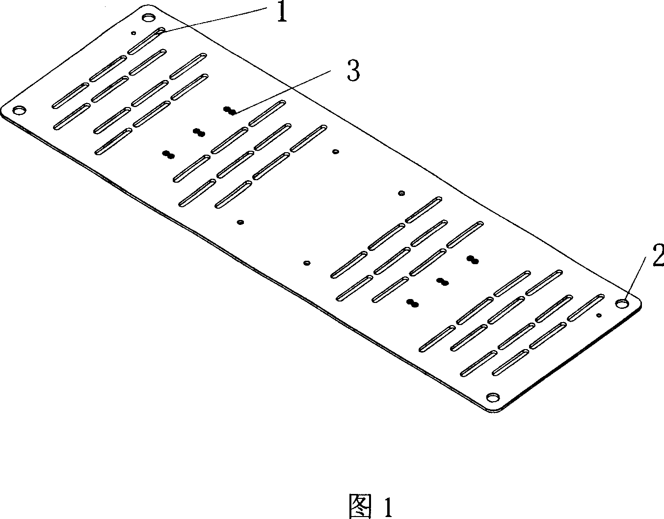
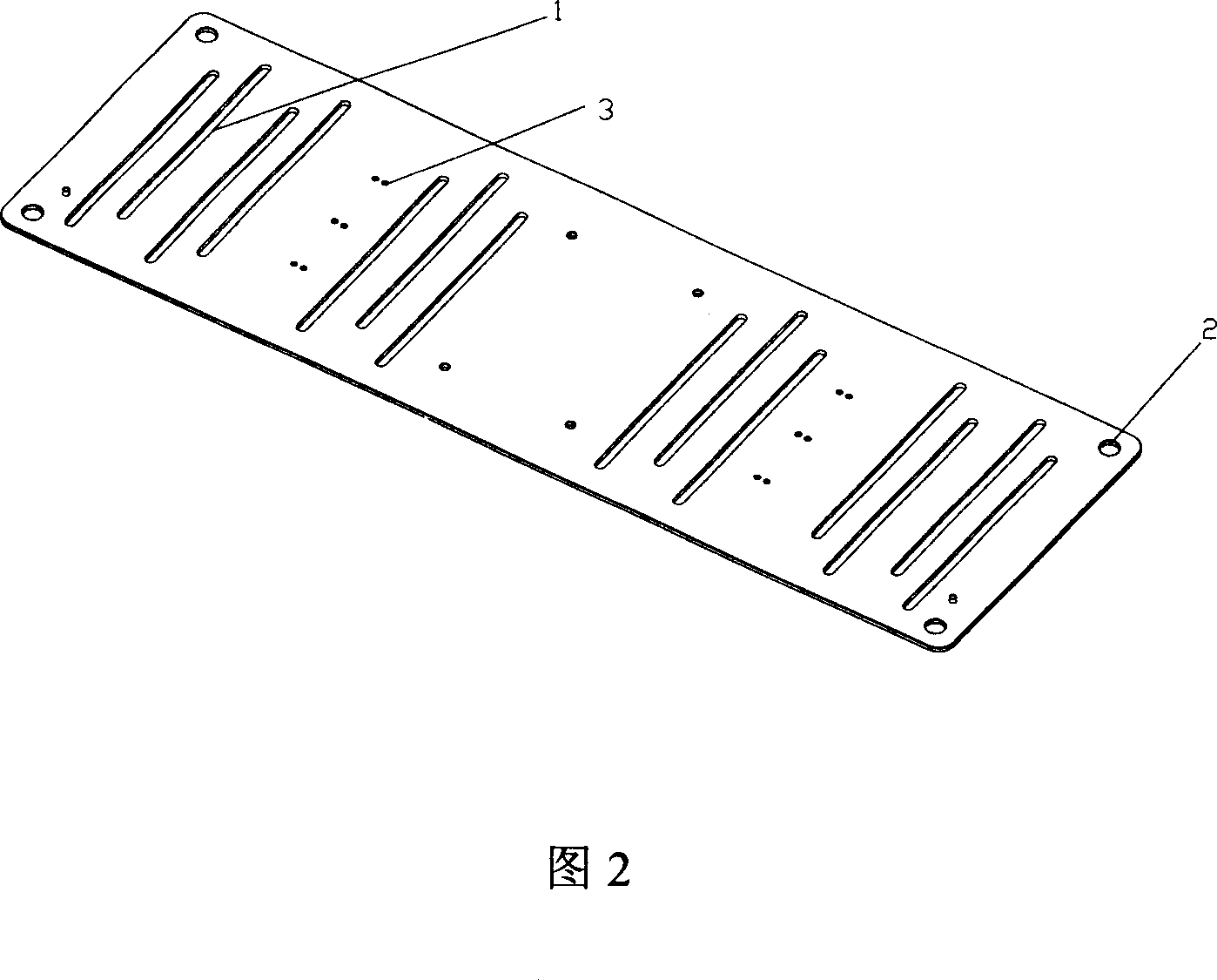
[0019] As shown in FIG. 1 , a workstation panel used in a disk production workshop is preferably implemented. The panel is provided with a gas guide groove 1 , a panel positioning hole 2 and a fixture installation hole 3 . The gas diversion grooves are parallel to each other, and three gas diversion grooves are arranged at a parallel position. When the station panel is installed on the workbench, the groove direction and the conveying direction of the conveyor belt form an included angle which is preferably a right angle. In order to ensure that the airflow between two adjacent grooves will not inhibit each other, the distance between the parallel gas guide grooves is at least twice the narrow side of the grooves, which can form the effect of mutual promotion of the airflows and make the gas flow more smoothly. The gas diversion grooves are arrang...


PUM


Abstract

This invention discloses a station-type panel, in which, panel localization holes, clamp assembling hole and parallel gas diversion slots are set on the panel, and the direction of the slot forms an included angle with the delivery direction of a belt conveyer, which can reduce dust flowing onto the belt greatly.

Description

technical field [0001] The invention belongs to the field of auxiliary equipment for a production line in a clean room, and relates to an auxiliary equipment for a station panel on a production line in a clean room, in particular to a station panel used on a production line in a disk installation workshop. Background technique [0002] In the dust-free workshop or purification workshop, in order to prevent dust from flying and ensure a clean and dust-free production environment, the principle of internal air circulation is generally used to form the air supply and ventilation internal circulation in the workshop by using the airflow sent up and down. The vacuum cleaner sucks up the dust pressed down by the airflow. In the workshop, an assembly line is generally used to transfer the required components of each process to each station. In order to facilitate the flow of airflow from top to bottom, a large number of circular air guide holes are evenly arranged on the workbench ...

Claims


Application Information

Patent Timeline
IPC IPC(8): G11B5/84B08B15/00B65G45/10
Inventor 李源海
Owner YITUO SCI & TECH CO LTD SHENZHEN
Learn More