Shielding structure and communication apparatus

A technology of shielding structure and communication equipment, applied in the fields of magnetic field/electric field shielding, chassis/cabinet/drawer parts, electrical components, etc. It is impossible to solve small problems, so as to achieve the effect of improving the heat dissipation performance of the whole machine and reducing the cost of shielding.

Inactive Publication Date: 2007-10-31
GLOBAL INNOVATION AGGREGATORS LLC
View PDF0 Cites 2 Cited by
  • Summary
  • Abstract
  • Description
  • Claims
  • Application Information

AI Technical Summary

Problems solved by technology

[0004] However, this snap-in shielding structure, considering the processing technology, the depth H1 of the snap-in structure is 5mm to 10mm, so the flange value H2 of the snap-in slot cannot be made small, as shown in Figure 2. The schematic diagram of the connected shielding structure will cause the card slot 103 to block a part of the ventilation holes in the ventilation area 201 in the longitudinal direction. The shielding structure designed in this way blocks some of the ventilation holes and will affect the heat dissipation of the box.
Considering between the snap-in shielding structures, when the distance L3 between adjacent snap-in shielding structures is greater than 15mm, the shielding effectiveness will be greatly reduced, and the lateral dimension of the fan ventilation area 201 is far more than 15mm, so no matter whether two snap-in shielding structures When the shielding structure moves its position on the shell, its lateral direction will block a part of the ventilation holes in the ventilation area 201, thereby reducing the heat dissipation performance of the ventilation holes

Method used


Image

  • Shielding structure and communication apparatus
  • Shielding structure and communication apparatus
  • Shielding structure and communication apparatus

Examples


Embodiment Construction

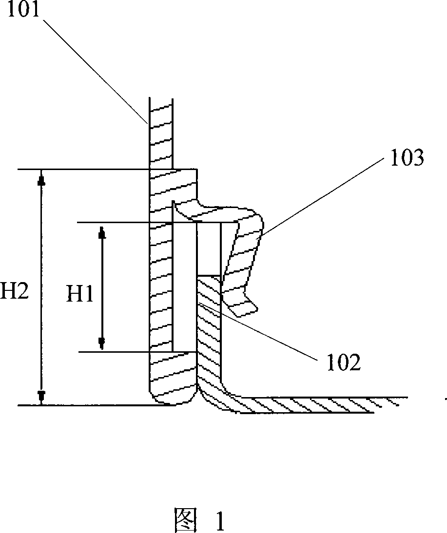
[0013] The embodiments of the present invention provide a shielding structure that does not block the ventilation holes of the box, thereby improving the heat dissipation performance of the box.

[0014] Embodiments of the present invention will be described in detail below in conjunction with the accompanying drawings.

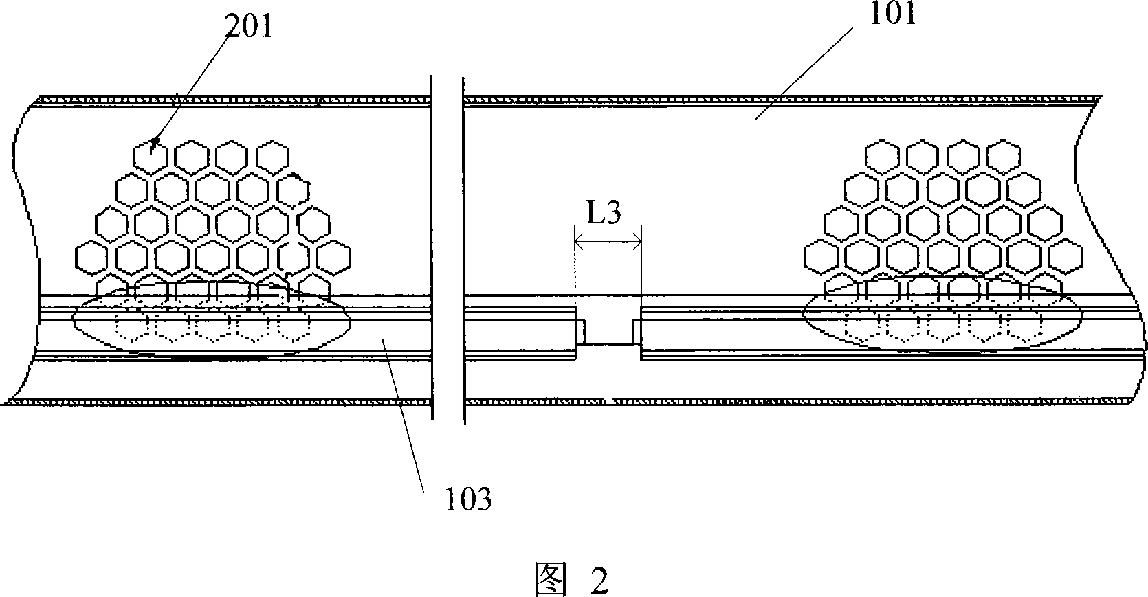
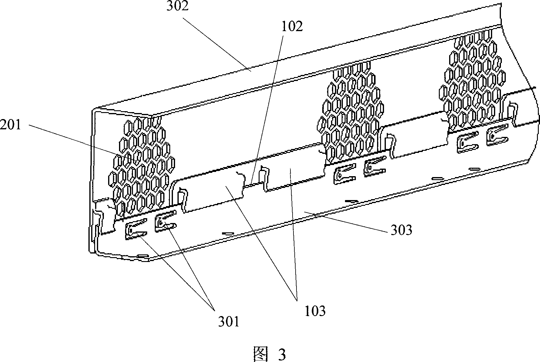
[0015] Please refer to FIG. 3 first. FIG. 3 shows a schematic diagram of a three-dimensional structure of a shielding structure according to an embodiment of the present invention, including a first housing 302 and a second housing 303. The first housing is provided with a plurality of ventilation holes to form a ventilation The area 201 is used to achieve internal and external ventilation to achieve the effect of heat dissipation; the part outside the ventilation area 201 is a non-ventilation area. The edge portions of the first housing 302 and the second housing 303 are overlapped, and an assembly component is provided at the overlapping portion to assemble...


PUM


Abstract

The invention discloses a shield structure that comprises the first shell and the second shell, said first shell possesses airways to form several aeration areas, assembly parts are set on edge of the first shell and the second shell outside of non aeration area, said assembly parts join the first shell and the second shell. The invention also disclose a communication shield equipment that comprises shield structure equipped on communication equipment, said shield structure includes the first shell and the second shell, said first shell possesses airways to form several aeration areas, assembly parts are set on edge of the first shell and the second shell outside of non aeration area, said assembly parts join the first shell and the second shell. With the invention, airways can not be warded, so radiating performance can be increased.

Description

technical field [0001] The invention relates to the technical field of electronic communication, in particular to a shielding structure of communication electronic equipment. Background technique [0002] In electronic products, it is often necessary to perform electromagnetic shielding on a certain part of the circuit. In the prior art, with the wide application of box-type shielding structures, the shielding effect of the product, the heat dissipation of the whole machine, the processing cost, processing technology, assembly technology, etc. Quality indicators are becoming more and more important. [0003] Figure 1 shows a schematic diagram of the existing snap-in shielding structure. Inside the box-type box, the second shell side of the box is connected to the box through the slot 103 provided on the side 101 of the first shell of the box The clamping plates 102 at the sides are clamped together. The clamping type shielding structure has reliable overlapping of componen...

Claims


Application Information

Patent Timeline
Patent Type & Authority Applications(China)
IPC IPC(8): H05K9/00H05K5/02
Inventor 刘桂玲敬美
Owner GLOBAL INNOVATION AGGREGATORS LLC
Why Eureka
Try Eureka