
Automatic monitoring system for engineering project deformation

An automatic monitoring and engineering technology, applied in measurement devices, surveying and navigation, height/level measurement, etc., can solve the problems of large maintenance works, difficult construction and installation, and high investment costs, achieving a high degree of automation, simple structure, Reliable effect

Inactive Publication Date: 2007-10-31
张立品 +1
View PDF0 Cites 33 Cited by
  • Summary
  • Abstract
  • Description
  • Claims
  • Application Information

AI Technical Summary

Problems solved by technology

[0003] Vacuum laser alignment system requires cooling equipment and maintains a certain degree of vacuum. It is difficult to construct and install, and it is difficult to guarantee the reset accuracy, sensitivity and vacuum degree of the wave zone plate for a long time. It affects the measurement of other measuring points. It is difficult to coordinate the cooling water and vacuum pump for a long time. If there is air leakage in the system or the reset failure of the wave zone plate, the maintenance project will be large.
The investment cost of the GPS automation system is relatively high. The total cost of the Geheyan system exceeds 6 million yuan. Excluding the software, since each deformation measurement point needs to be equipped with an antenna and a GPS receiver, the cost of a single point is also more than 200,000 yuan, and its measurement accuracy is affected. The location and measurement time have a great influence. For example, observations cannot be carried out in the corridor. To obtain accurate measurement values ​​of the measurement points, the measurement time will be longer. More importantly, the GPS satellites are launched by the US government for military purposes. From a strategic perspective Generally speaking, the monitoring of reservoirs, dams, and bridges in a country cannot rely on this method

Method used


Image

  • Automatic monitoring system for engineering project deformation
  • Automatic monitoring system for engineering project deformation
  • Automatic monitoring system for engineering project deformation

Examples


Embodiment Construction

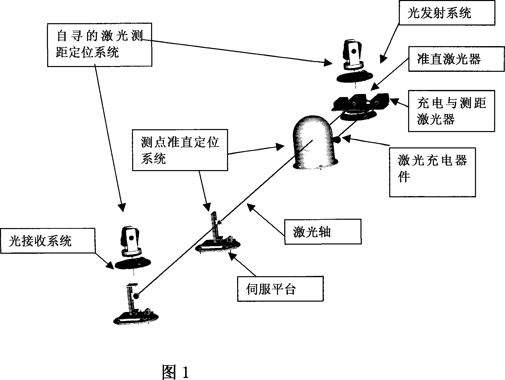
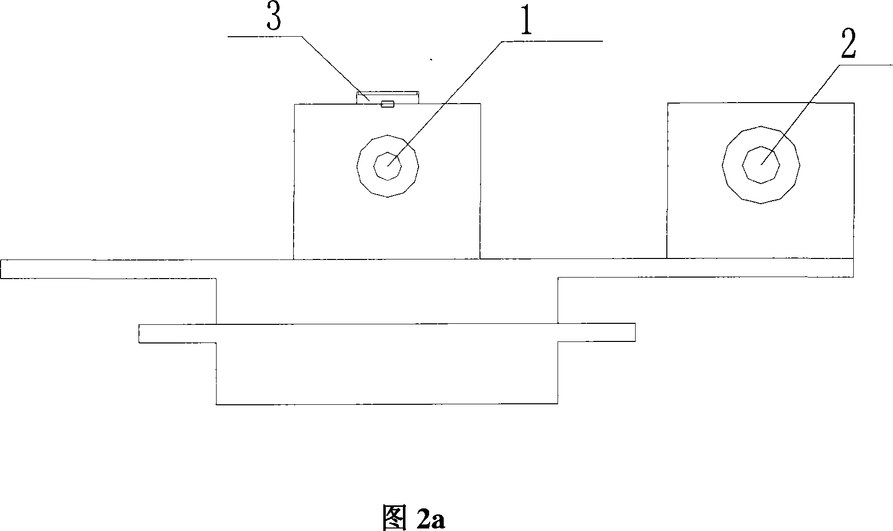
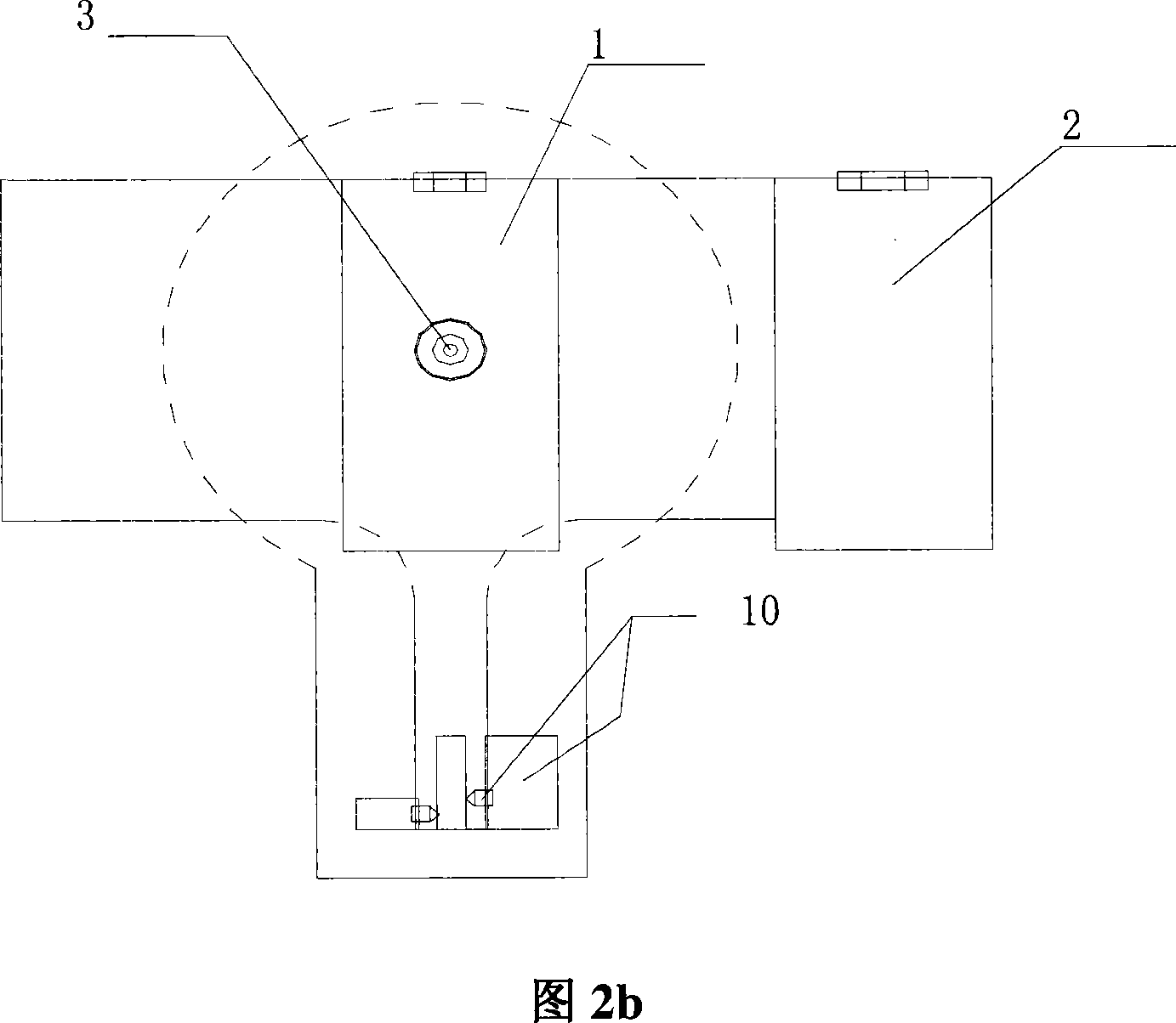
[0017] The present invention will be described in further detail below in conjunction with the accompanying drawings: As shown in Figure 1, the present invention provides a kind of automatic deformation monitoring system that is used for large-scale engineering body based on laser collimation, and this system is made up of light emitting system, light receiving system The positioning system, point alignment and positioning system, self-seeking laser ranging and positioning system are composed of MCU control and CPU control, energy system, and environment maintenance system. The light emitting system and the light receiving positioning system are respectively installed at both ends of the project body. These two systems establish a horizontal collimated laser axis, use the deformation control network around the large engineering body (the control network is usually controlled by a higher-level control network), and the self-seeking laser ranging and positioning system The spatia...


PUM


Abstract

This invention relates to one engineer automatic monitor system for one monitor system based on laser calibration, which comprises light emission system, light receive position system, test calibration position system, self-searching laser distance and position MCU control and CPU control, energy system and environment sustaining system, wherein the engineer part both ends are fixed with emission system and receive position system to establish one level calibration laser axis to determine laser axis space line equation by use of engineer circle deformation and laser test and positioning system; the calibration position system is distributed on monitor points to be tested along laser axis for cross and level displacement; when rain fall on sensor, CPU sends signal to each sub system to close its sub system cover.

Description

technical field [0001] The invention relates to an automatic monitoring system used in engineering, and is especially suitable for a fully automatic deformation monitoring system for large engineering bodies based on laser alignment. Background technique [0002] The current safety assessment of dams, reservoirs, bridges and other engineering bodies mainly depends on deformation monitoring data, such as horizontal displacement, vertical displacement, deflection, inclination, surface joints and cracks, etc. The monitoring methods of horizontal displacement mainly include: movable target method, small angle method, positive and negative vertical line, tension line, vacuum laser alignment method, front intersection method and wire method, etc. The monitoring methods of vertical displacement mainly include: precision level, static level, triangular elevation, connected tube vacuum laser alignment method, etc. These methods were initially measured manually by optical instruments...

Claims


Application Information

Patent Timeline
Patent Type & Authority Applications(China)
IPC IPC(8): G01C5/00G01B11/16
Inventor 张立品金连河
Owner 张立品
Learn More