Filter assembly for sampling

A filter and filter cartridge technology, applied in sampling, fixed filter element filter, filtration and separation, etc., can solve the problem of frequent renewal of filter media, achieve excellent cleaning performance, prevent filter residue deposition, reliable and continuous sample delivery. Effect

Active Publication Date: 2007-10-24
METSO OUTOTEC (FINLAND) OY
View PDF1 Cites 4 Cited by
  • Summary
  • Abstract
  • Description
  • Claims
  • Application Information

AI Technical Summary

Problems solved by technology

However, rapid filter residue deposition still occurs in the filter assembly of US Patent 3674153, and the filter media still needs to be frequently refreshed

Method used


Image

  • Filter assembly for sampling
  • Filter assembly for sampling
  • Filter assembly for sampling

Examples


Embodiment Construction

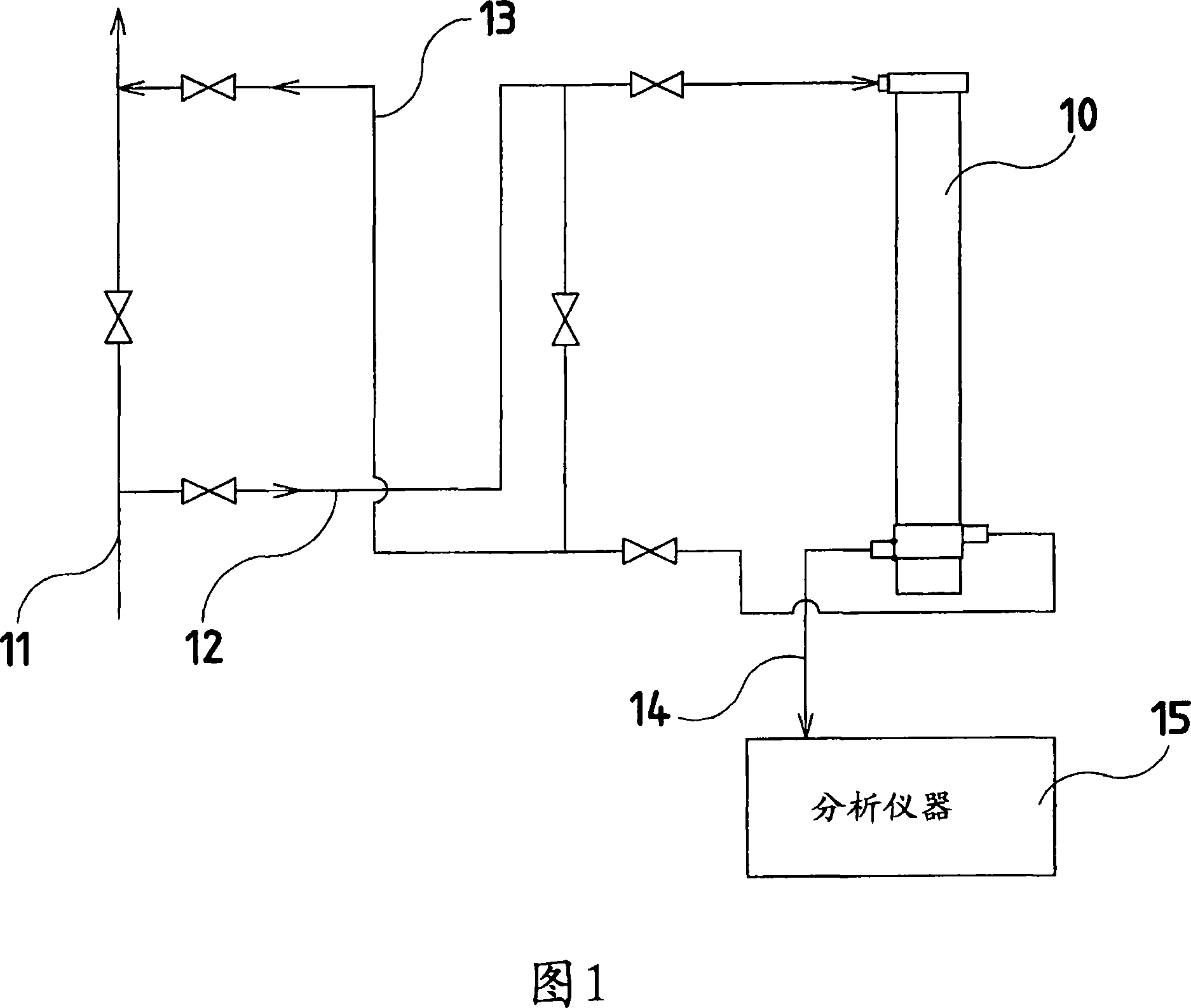
[0018] Figure 1 shows a simplified diagram of a possible connection of a filter assembly according to the invention between a process stream and an analytical instrument. The filter device 10 preferably works in a vertical position. A stream 12 is withdrawn from the main production stream 11 and directed to an inlet provided at the upper end of the filtering device 10 . The liquid stream 13 flowing through the spiral channel of the filter device 10 and out of the slurry outlet returns to the main production liquid stream 11 . Filtered sample stream 14 flows forward to analytical instrument 15 . Filter assemblies provide small amounts of filtered samples to analytical instruments and return large amounts of collected samples to production. The analytical instrument may include a pneumatic sample delivery station to deliver the filtered sample to the analytical chamber of the analytical instrument.

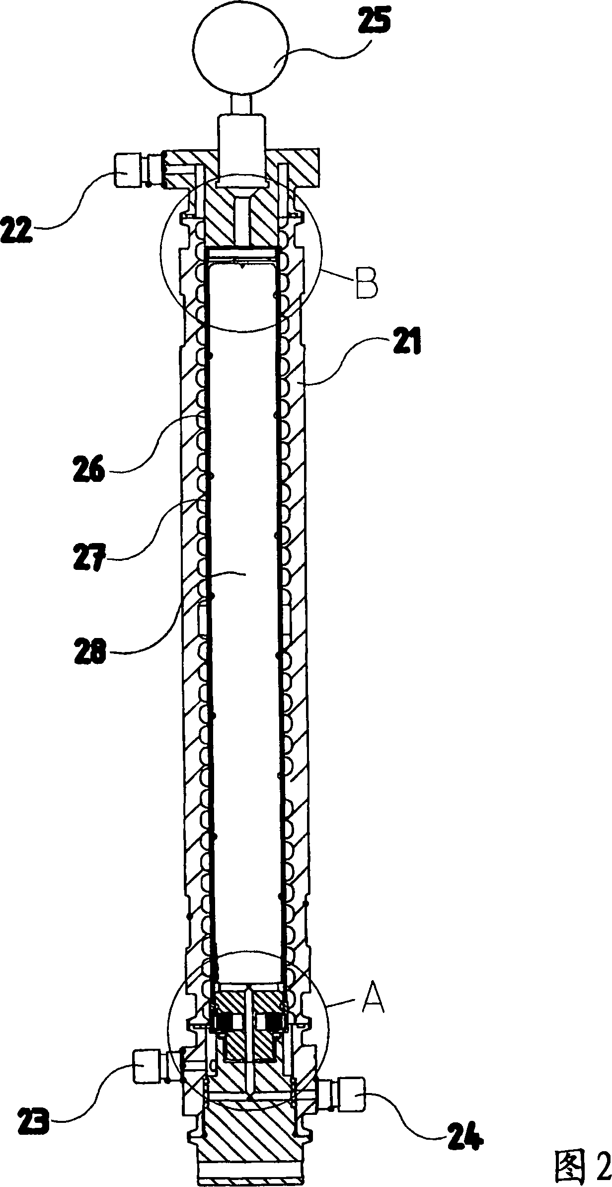
[0019] Fig. 2 is a cross-sectional view of an embodiment of a filtering devi...


PUM

PropertyMeasurementUnit
Spacingaaaaaaaaaa

Abstract

A filter assembly is provided for obtaining a filtered liquid sample from slurry, such as a liquid process stream that contains liquid, dissolved matter and solids. A housing (21) defines a cavity. A rod (28) is arranged in the cavity and supports a filter (49) . A cartridge (27) comprises the filter (49) , and is arranged between the housing (21) and the rod (28) . Furthermore, there is a helicoidal passage for a slurry defined by the housing and the cartridge. There is also a cavity defined by the rod and the cartridge. The slurry has velocity that generates scouring and cleaning action on the filter media thus preventing cake formation on the filter. The filtering apparatus of the present invention provides reliable and continuous on-line sample delivery for an analyzer.

Description

technical field [0001] The present invention relates to the field of solid-liquid separation using filtration. More particularly, the present invention relates to a method and apparatus for obtaining filtered samples from industrial process streams including liquids, dissolved substances and solids. Background technique [0002] In manufacturing processes involving the handling and processing of solids containing liquids, it is often necessary to periodically and continuously control the process. Several analytical methods currently in use are performed only with liquids free of solids. These methods are, for example, optical analysis, conductivity measurement, pH measurement and methods using X-rays, such as X-ray fluorescence analysis. In order to monitor rapidly evolving industrial processes and to control them optimally based on the results of these measurements, it is necessary to continuously take samples from industrial process streams and analyze them immediately w...

Claims


Application Information

Patent Timeline
IPC IPC(8): B01D35/22G01N1/20B01D29/15G01N1/28G01N1/34
CPCG01N1/2035B01D29/15G01N1/34G01N1/4077B01D29/902B01D29/908Y02P10/20B01D35/22
Inventor V·萨里宁
Owner METSO OUTOTEC (FINLAND) OY
Why Eureka
Try Eureka