A backlight brightness adjustable drive circuit

A driving circuit and backlight brightness technology, which is applied in the directions of optics, light source, electric light source, etc., can solve the problems of increasing the difficulty of integrated design of driving circuit and increasing the production cost of equipment, so as to achieve the effect of simple implementation and reduced use

Inactive Publication Date: 2007-10-24
ACTIONS ZHUHAI TECH CO
View PDF0 Cites 11 Cited by
  • Summary
  • Abstract
  • Description
  • Claims
  • Application Information

AI Technical Summary

Problems solved by technology

At present, the function of real-time and uninterrupted generation of PWM pulse signals needs to be completed by a separate electronic component in most cases. Cost of production

Method used


Image

  • A backlight brightness adjustable drive circuit
  • A backlight brightness adjustable drive circuit
  • A backlight brightness adjustable drive circuit

Examples


Embodiment Construction

[0028] In order to make the above objects, features and advantages of the present invention more comprehensible, the present invention will be further described in detail below in conjunction with the accompanying drawings and specific embodiments.

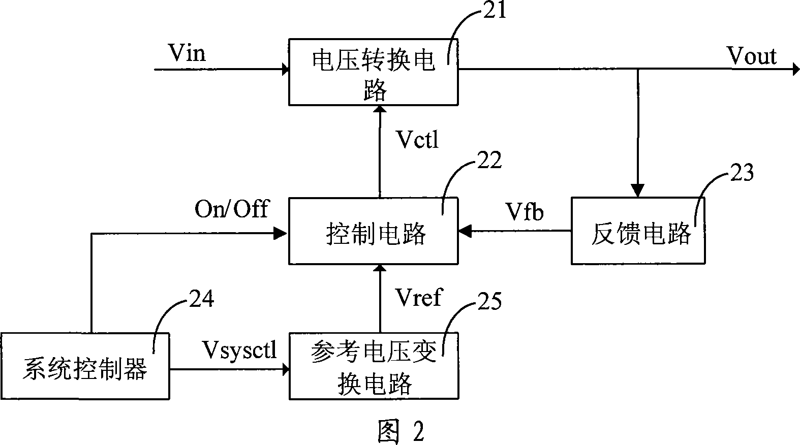
[0029] Referring to FIG. 2 , it is a schematic structural diagram of a driving circuit for backlight brightness adjustment provided by the first embodiment of the present invention, including a voltage conversion circuit 21 , a control circuit 22 , a feedback circuit 23 , a system controller 24 , and a reference voltage conversion circuit 25 .

[0030] The system controller 24 generates a digital control signal Vsysctl and sends the digital control signal Vsysctl to the reference voltage conversion circuit 25 . The system control controller 24 controls the on and off of the control circuit 22 at the same time. The system controller 24 can be a general-purpose signal processor such as ARM or MIPS or other general-purpose DSP, or va...


PUM


Abstract

The related drive circuit for back light adjustment comprises; a voltage conversion circuit, a control circuit generating control signal, a system controller, a feedback circuit obtaining working voltage from the voltage conversion circuit and conversing into the feedback signal for last circuit, and a reference voltage conversion circuit receiving and conversing control signal into reference voltage. This invention reduces cost, and has well integration level.

Description

technical field [0001] The invention relates to the field of electronic circuits, in particular to a driving circuit for adjusting the brightness of a backlight. Background technique [0002] The display brightness of display devices such as LCDs on electronic equipment often needs to be adjusted adaptively to facilitate viewing by human eyes. At present, most existing driving circuits for adjusting the brightness of the backlight adopt the method of changing the output / input ratio relationship of the feedback loop to adjust the output of the driving circuit, thereby controlling the brightness of the backlight. [0003] Referring to FIG. 1 , it is a structural schematic diagram of a conventional driving circuit for adjusting backlight brightness, including a voltage conversion circuit 11 , a control circuit 12 , a feedback circuit 13 , and a system controller 14 . The system control controller 14 outputs a control signal Wctl in the form of a PWM pulse to the feedback circu...

Claims


Application Information

Patent Timeline
Patent Type & Authority Applications(China)
IPC IPC(8): H05B41/38G02F1/13357G02F1/1335
Inventor 顾明仁李鑫
Owner ACTIONS ZHUHAI TECH CO
Why Eureka
Try Eureka