
A system and method for improving the multiplex section switching correctness

A multiplexing section and correctness technology, applied in the field of optical transmission systems, can solve problems such as service interruption time exceeding the limit, K byte error code, protocol module reset, etc., to improve switching correctness, improve stability, and reduce multiplexing Effect of Segment Switching Error

Inactive Publication Date: 2011-05-11
ZTE CORP
View PDF2 Cites 0 Cited by
  • Summary
  • Abstract
  • Description
  • Claims
  • Application Information

AI Technical Summary

Problems solved by technology

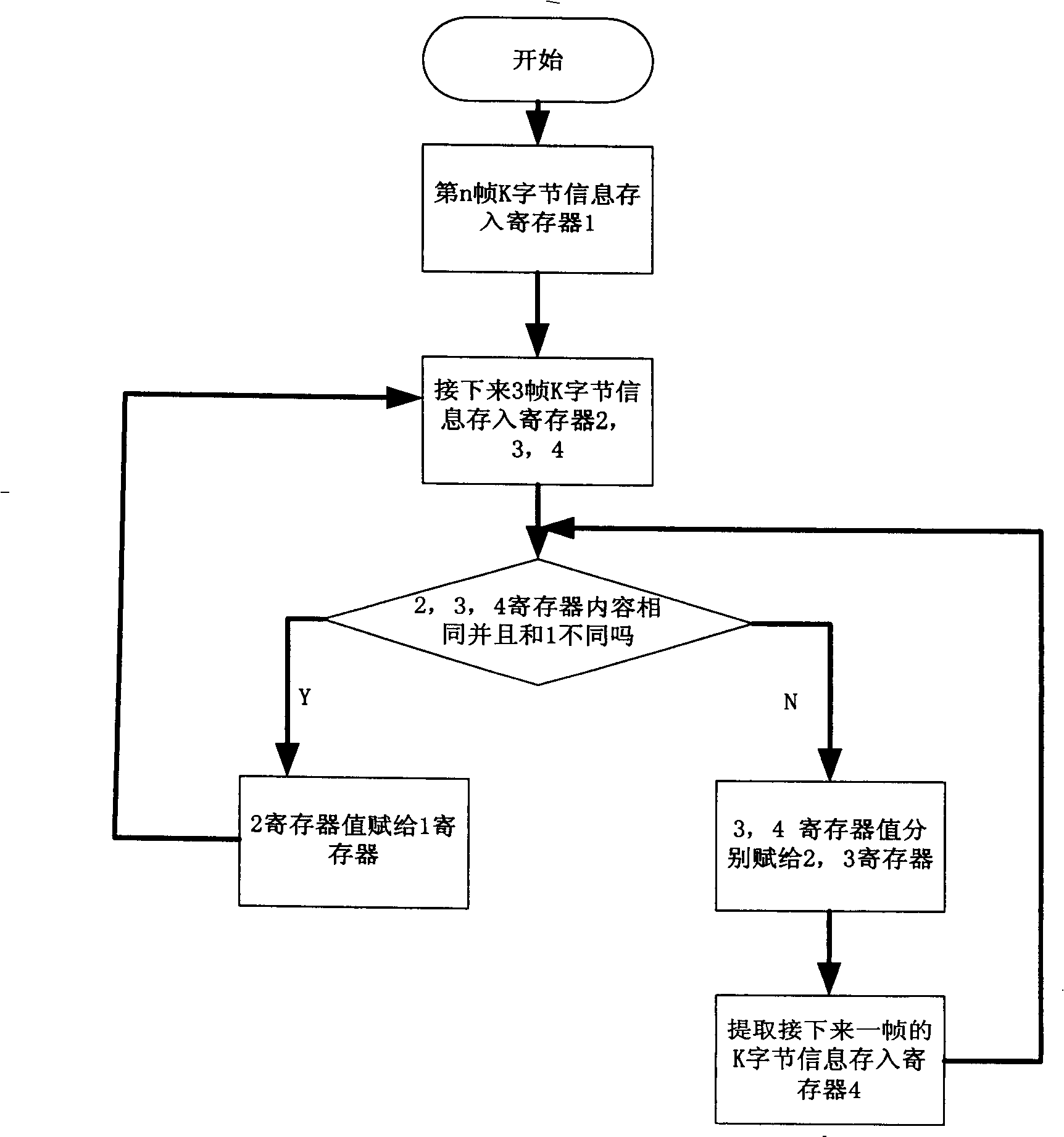
[0007] Due to the difference in the processing speed of software and hardware, the K1 and K2 bytes sent by the software are sequential. The peer optical line unit checks the received K1 and K2 respectively, which can meet the requirements of K1 for 3 consecutive frames and K2 for 3 consecutive frames. , there is no problem, and the K1 and K2 are sent to the FPGA array of the local protocol processing part, and the FPGA can detect the change of K1 or K2 within one frame. At this time, it is likely that the sending end sends K2 slower than K1 In the case of 1 to 2 frames, it may happen that the change of K1 has been confirmed, but the change of K2 has not yet been confirmed. At this time, the protocol module thinks that the new K1 has taken effect, but the information of K2 is still old. Such a combination produces Bit errors in K bytes cause problems such as protocol module reset and service interruption time exceeding the limit.
[0008] The above analysis proves that K-byte sending and detection changes are both processed by software, and there will still be K-byte errors similar to this situation, but the probability is smaller, so the original processing method has inherent defects, but in the existing In the process of technological improvement, this defect has reached the point where it must be corrected.

Method used


Image

  • A system and method for improving the multiplex section switching correctness
  • A system and method for improving the multiplex section switching correctness
  • A system and method for improving the multiplex section switching correctness

Examples


Embodiment Construction

[0028] Various preferred embodiments of the present invention will be described in detail below in conjunction with the accompanying drawings.

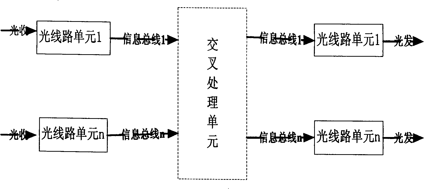
[0029] The hardware part of the system of the present invention sees figure 1 As shown, it includes a cross processing unit, an information bus, an optical line unit and a backplane.

[0030] The backboard is fixed on a subrack, the single boards are inserted into the corresponding slots of the backboard, and the single boards are connected to each other through the bus of the backboard.

[0031] Such as figure 1 As stated above, the optical line unit enters the K-byte verification state after it is officially started, and the optical line processing unit only verifies the K-byte information in the receiving direction of the optical port. Said optical line unit FPGA does not carry out the verification of K bytes in the initialization stage, because the device of optical line unit has not entered the official working state at this ti...


PUM


Abstract

The disclosed method in this invention comprises: A. in all process unit FPGA, adding K bytes combined check toward optical receiving direction; and B. FPGA checks the received every K-byte message and successive two group K-byte message, decides the message stably if consistent, and sends message to the cross-process unit through bus. This invention uses K1 and K2 for combined check, reduces themultiplex switch error greatly, and then improves transmission network stability and reliability.

Description

technical field [0001] The present invention relates to an optical transmission system and method, in particular to a method for eliminating code errors of K bytes (including protection extension K bytes, consisting of K1, K2 and extensions K1, K2) to improve the correctness of multiplex section protection systems and methods. Background technique [0002] In the prior art, the multiplex section protection switching is a method to realize the self-healing function of the transmission network, and improving the correctness of the multiplex section switching is to improve the network performance. The multiplex section switching is realized by transmitting protocol information of K bytes, and K-byte bit errors affect the correctness of the multiplex section switching, which may lead to interruption of transmission services and cause serious economic losses. [0003] However, during the transmission of K bytes, it is easy to generate K bytes errors due to line interference, opt...

Claims


Application Information

Patent Timeline
Patent Type & Authority Patents(China)
IPC IPC(8): H04B10/00H04Q11/00H04B10/032
Inventor 关鲁君杨昭霞陆波
Owner ZTE CORP
Learn More