Long size element for suspending ceiling

A ceiling and long ruler technology, applied in building components, buildings, ceilings, etc., can solve problems such as the reduction of durability strength, and achieve the effect of reducing painting operations.

Inactive Publication Date: 2007-10-17
OKUMURA SEISAKUSHO
View PDF1 Cites 2 Cited by
  • Summary
  • Abstract
  • Description
  • Claims
  • Application Information

AI Technical Summary

Problems solved by technology

At the support end portion 82 of this one plate, the force supporting the ceiling support portion 78 has a limit. If the above-mentioned static load and repeated load act f

Method used


Image

  • Long size element for suspending ceiling
  • Long size element for suspending ceiling
  • Long size element for suspending ceiling

Examples


no. 1 example

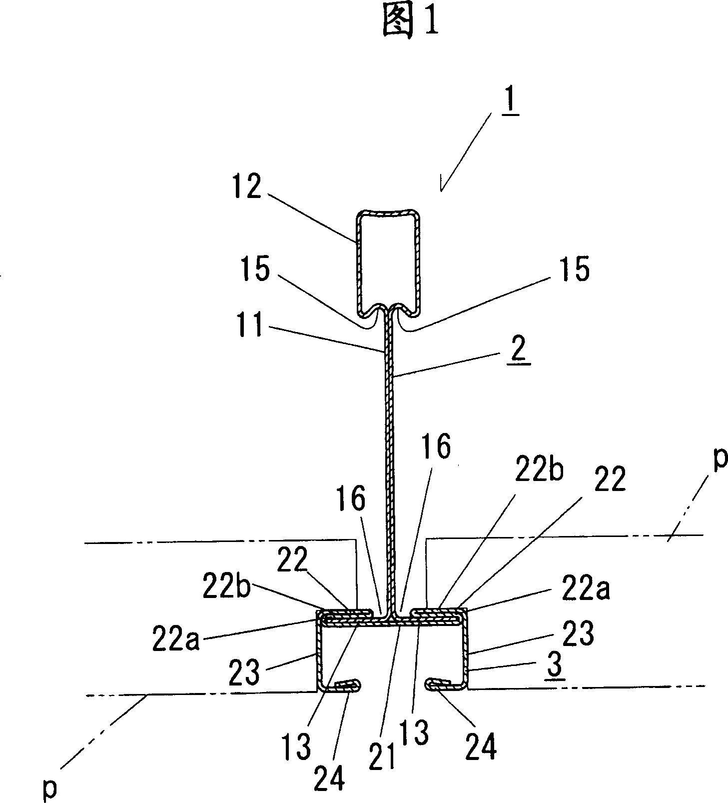
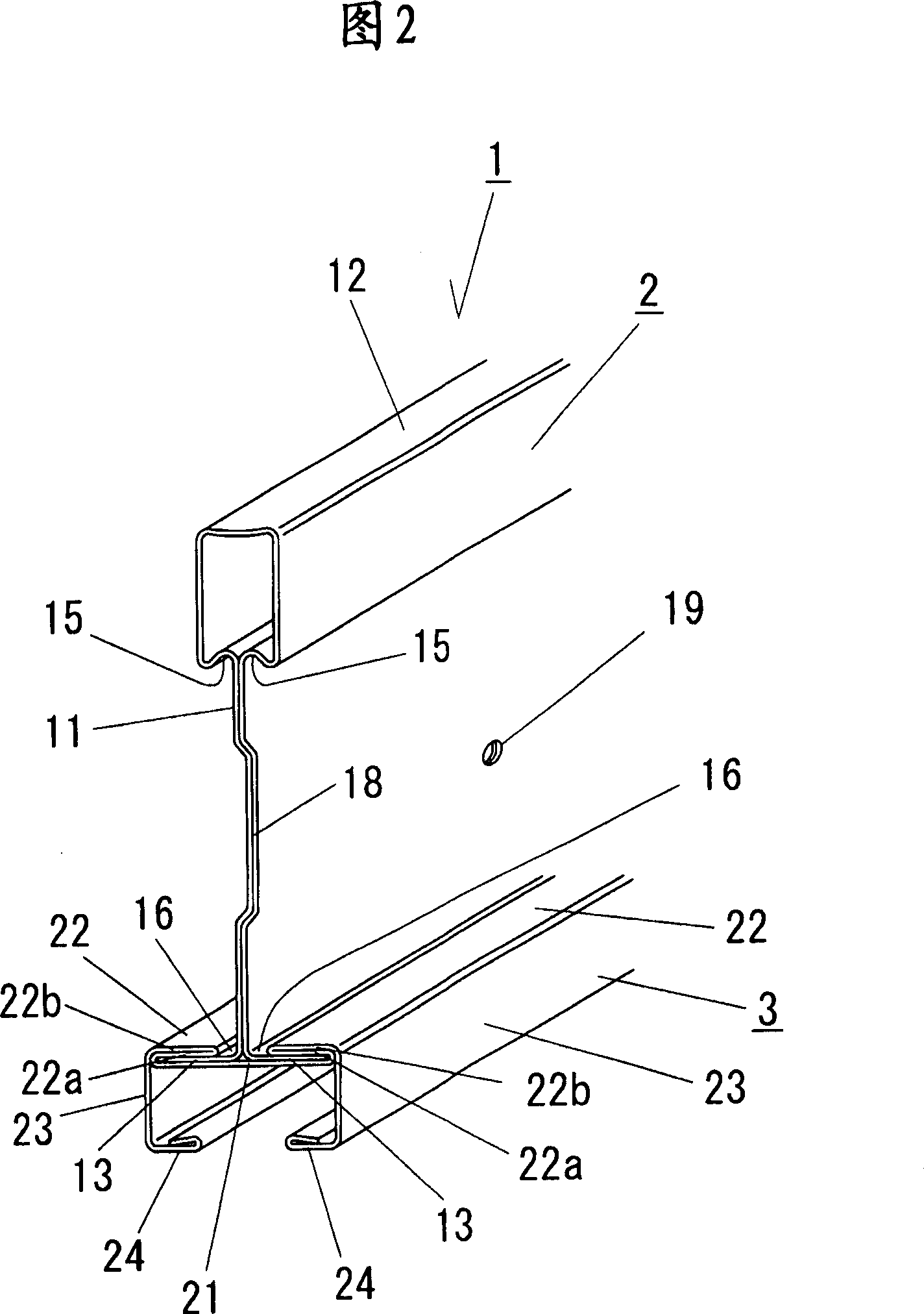
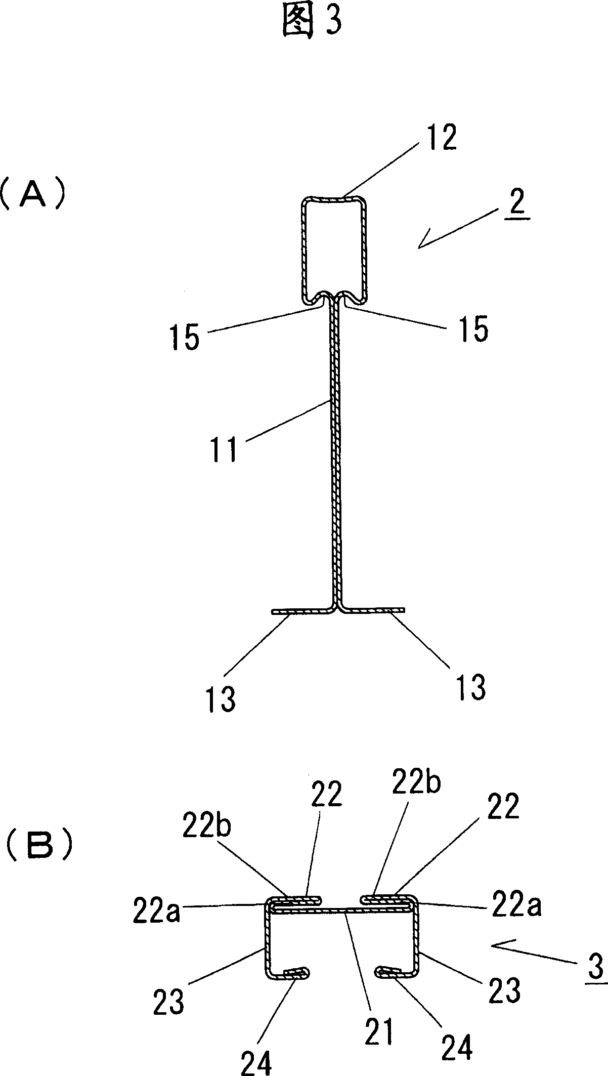
[0055] As shown in Figures 1 to 3, the elongated member 1 for suspending the ceiling of the first embodiment is integrally formed by combining a suspending rod 2 with an inverted T-shaped section and a locking beam 3 with a U-shaped section.

[0056]The above-mentioned suspension rod 2 is formed of a long substantially rectangular steel plate, and its cross-sectional shape is mirror-symmetrical with respect to the center line. The suspension bar 2 is processed into an inverted T-shaped cross section by stamping a steel plate, and is composed of a locking raised portion 12 , a vertical side portion 11 , and horizontal engaging portions 13 , 13 . Here, the vertical side portion 11 is formed by stacking steel plates so that both sides of the longitudinal center line are partially back-to-back, and formed into two plates in the vertical direction. The locking protrusions 12 respectively extend from the upper ends of the two plates constituting the vertical side portion 11, and are...

no. 2 example

[0092] As shown in Figures 13 to 15, the elongated member 101 for suspending the ceiling of the second embodiment is integrally formed by combining a suspending rod 102 with an inverted T-shaped section and a locking beam 103 with a substantially U-shaped section. . The suspension rod 102 is the same as the above-mentioned first embodiment, and is formed by bending a substantially rectangular steel plate through roll forming, and consists of a locking raised portion 12, a vertical side portion 11, and a horizontal engaging portion 113. , 113 constitute.

[0093]Here, the horizontal engaging portions 113, 113 are bent and formed with ribs protruding upward (on the side of the locking raised portion 12) along the longitudinal direction at a position having a predetermined interval in the horizontal direction from the lower end of the vertical side portion 11. Section 115, 115. The rib 115 of the horizontal engaging portion 113 is bent into a mountain-shaped cross-section protr...


PUM


Abstract

The invention provides a long size element for suspending ceiling with high strength and endurance strength capable of supporting the ceiling long and steadily. The clamping determinate beam (3), whose section is approximately cross-sectional type, has supporting lower side part (21) attached under horizontal engagement part (13, 13) of the steeve (2) with a inverted T-type section, and supporting double-deck side parts (22, 22) retracing from two outer ends of the supporting lower side part (21) and extending inward in the way of covering the horizontal engagement part (13, 13) and retracing to extend outward and cascading. The clamping determinate beam (3) and the steeve (2) are integrated by using supporting lower side part (21) and supporting double-deck side parts (22, 22) on either side to hold the horizontal engagement part (13, 13), thereby developing high strength and endurance strength of static load and repeating load generated by enduring self weight of the ceiling (P), being capable of supporting the ceiling (P) long, steadily and properly.

Description

technical field [0001] The present invention relates to an elongated member for suspending a ceiling assembled in a lattice shape and used for suspending a ceiling. Background technique [0002] As shown in Fig. 17 and Fig. 18, the elongated member f for suspending the ceiling is formed as follows, that is, a vertical side t is formed in a substantially vertical direction, and a hook j for fixing a hook is formed at the upper end of the vertical side t. The cross-section is a rectangular ring-shaped locking raised portion i, and the lower end of the vertical side portion t is formed with a U-shaped locking edge portion g with a U-shaped cross-section. The elongated member f for suspending the ceiling is assembled in a lattice shape, and supports the side end portions of the ceiling p on both upper surfaces of the above-mentioned locking edge portion g. And the indoor ceiling is comprised by supporting the some ceiling p in a row. In addition, generally, the elongate materi...

Claims


Application Information

Patent Timeline
IPC IPC(8): E04B9/06E04B9/28
Inventor 奥村昌弘
Owner OKUMURA SEISAKUSHO
Why Eureka
Try Eureka