Heat radiation fin

A technology of heat dissipation fins and heat sinks, applied in cooling/ventilation/heating transformation, instrument cooling, instruments, etc., can solve the problems of bending and deformation of heat sink 20, affecting heat dissipation effect, impracticality, etc., and achieves stable structure and easy disassembly Easy Action, High Quality Effects

Inactive Publication Date: 2007-10-10
LUHE ENTERPRISES
View PDF0 Cites 5 Cited by
  • Summary
  • Abstract
  • Description
  • Claims
  • Application Information

AI Technical Summary

Problems solved by technology

More seriously, it will also cause the problem of bending and deformation of the heat sink 20, which will cause the overall flatness of the heat dissipation fin group, or the shortcomings of ...

Method used


Image

  • Heat radiation fin
  • Heat radiation fin
  • Heat radiation fin

Examples


Embodiment Construction

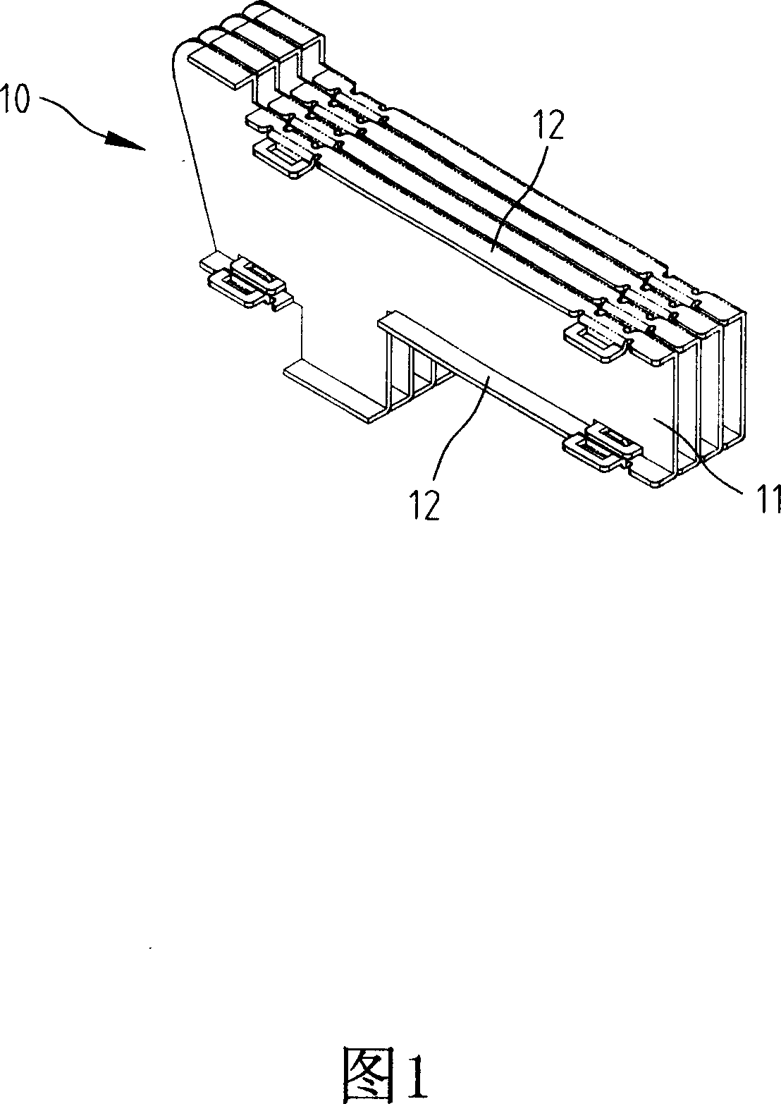
[0025] Referring to Fig. 1, the cooling fins of the present invention are formed by combining multiple cooling fins 10; wherein:

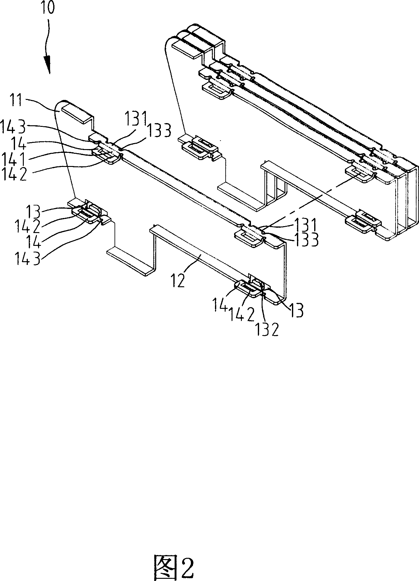
[0026] Referring to FIG. 2 and FIG. 3 , this embodiment illustrates a situation in which multiple heat sinks 10 can be disassembled and assembled with each other. The number of assembled fins in actual use is not a feature of this case and is not limited by this embodiment. The heat sink 10 has a bottom wall 11, and a plurality of vertically extending side walls 12 are respectively formed on the upper and lower sides of the bottom wall 11, and several engaging grooves 13 are formed at the turning points of the bottom wall 11 and the side walls 12. , and the sidewalls 12 are protrudingly provided with several clips 14 snapped into the clip slots 13 .

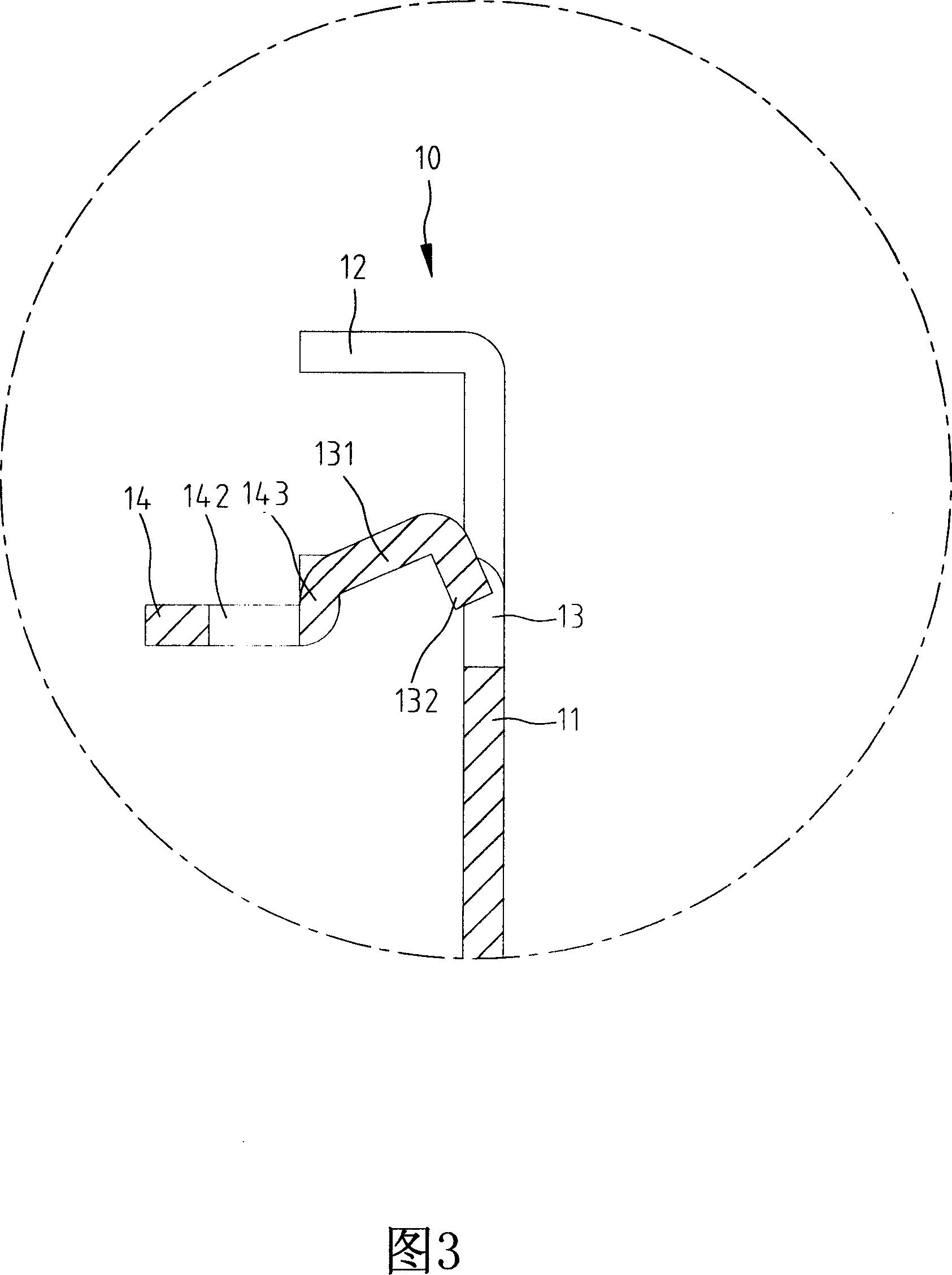
[0027] An inserting portion 131 extending from the side wall 12 is provided in the snap-in slot 13 , and an inserting end 132 is formed at the end of the inserting portion 131 with a 90-degree turn. T...


PUM


Abstract

The invention comprises multi pins connected each other. Said fins have a lower wall and a side wall extending at the side edge of the lower wall. It features multi female clamping slots located at the lower wall, and multi male clamping pieces located on the side wall and used for plugged into the female clamping slot; said female clamping slots have a plug; said male clamping pieces has a jack used for holding the plug.

Description

technical field [0001] The invention relates to a heat dissipation fin, in particular to a heat dissipation fin which can be easily disassembled and assembled and is not easily deformed and damaged. Background technique [0002] At present, the central processing unit of the computer is also responsible for calculating a large number of electronic signals. In order to effectively process astronomical data, the heat generated by the central processing unit is quite high, and the heat must be quickly taken away from the central processing unit. In order to avoid the problem that the operating efficiency is reduced and the central processing unit stops working or is damaged. [0003] In order to effectively discharge the heat energy generated by the central processing unit, many structures have been widely used on the market, such as the design of heat sinks, including heat sinks of aluminum extrusion type, die-casting type, etc., and the heat sink of this type The cooling eff...

Claims


Application Information

Patent Timeline
IPC IPC(8): H05K7/20H01L23/36G06F1/20G12B15/06
Inventor 林朝吉
Owner LUHE ENTERPRISES
Why Eureka
Try Eureka