Power converter

A power conversion device and power terminal technology, which is applied to output power conversion devices, circuits, electrical components, etc., can solve the problems of periodic on-off duty cycle limitation, high price, unavoidable enlargement and cost increase, etc. low cost effect

Inactive Publication Date: 2007-10-03
HITACHI LTD
View PDF2 Cites 2 Cited by
  • Summary
  • Abstract
  • Description
  • Claims
  • Application Information

AI Technical Summary

Problems solved by technology

[0004] Current sensors used in power conversion devices are generally required to be small, low-loss, low-cost, and high-precision. It cannot be said that these aspects have been fully considered in the prior art
[0005] In the prior art described above, in addition to the high price of the current sensor with the insulated magnetic core itself, as a path for the primary current, it is necessary to pass through structures such as the bus bar of the sensor, so the number of parts increases and the structure is enlarged. , thus further increasing the cost
[0006] Furthermore, from the viewpoint of system protection against overcurrent such as short circuits, it is necessary to provide a current detection circuit for detecting overcurrent of switching elements in addition to a current sensor for detecting output current, which not only increases the number of parts, but also makes it impossible Avoid further escalation of costs
[0007] In addition, since the current sensor based on the shunt resistance increases the power loss in equipment that controls a large current such as a power conversion device, it is necessary to consider the increase in the size of the shunt resistor and suppress the temperature rise due to heat generation. Unavoidable increase in size and cost
[0008] From these aspects, in the above-mentioned prior art, although it is expected to perform current detection using the on-voltage of the MOSFET, at this time, it is necessary to make the element in the on-state at the timing (timing) to detect the current, so the cycle of current detection and on-off duty will be mutually limited
[0009] For example, when the current detection is performed by the lower arm, the lower arm needs to be fully turned on every current detection cycle, so the current detection cannot be performed in the state where the upper arm is 100% turned on.
Moreover, it takes time from the moment the lower arm is turned on until the output of the current value stabilizes, and the sampling of the current value also takes time, so it is necessary to lengthen the on-period of the lower arm. more restrictive
[0010] Thus, when the duty ratio has an upper limit value, the output voltage performance of the power conversion device is limited, for example, in the case of an inverter driving a three-phase motor, the voltage applied to the motor is limited, resulting in The disadvantage that current does not flow under high-speed rotation

Method used


Image

  • Power converter
  • Power converter
  • Power converter

Examples


Embodiment approach 1

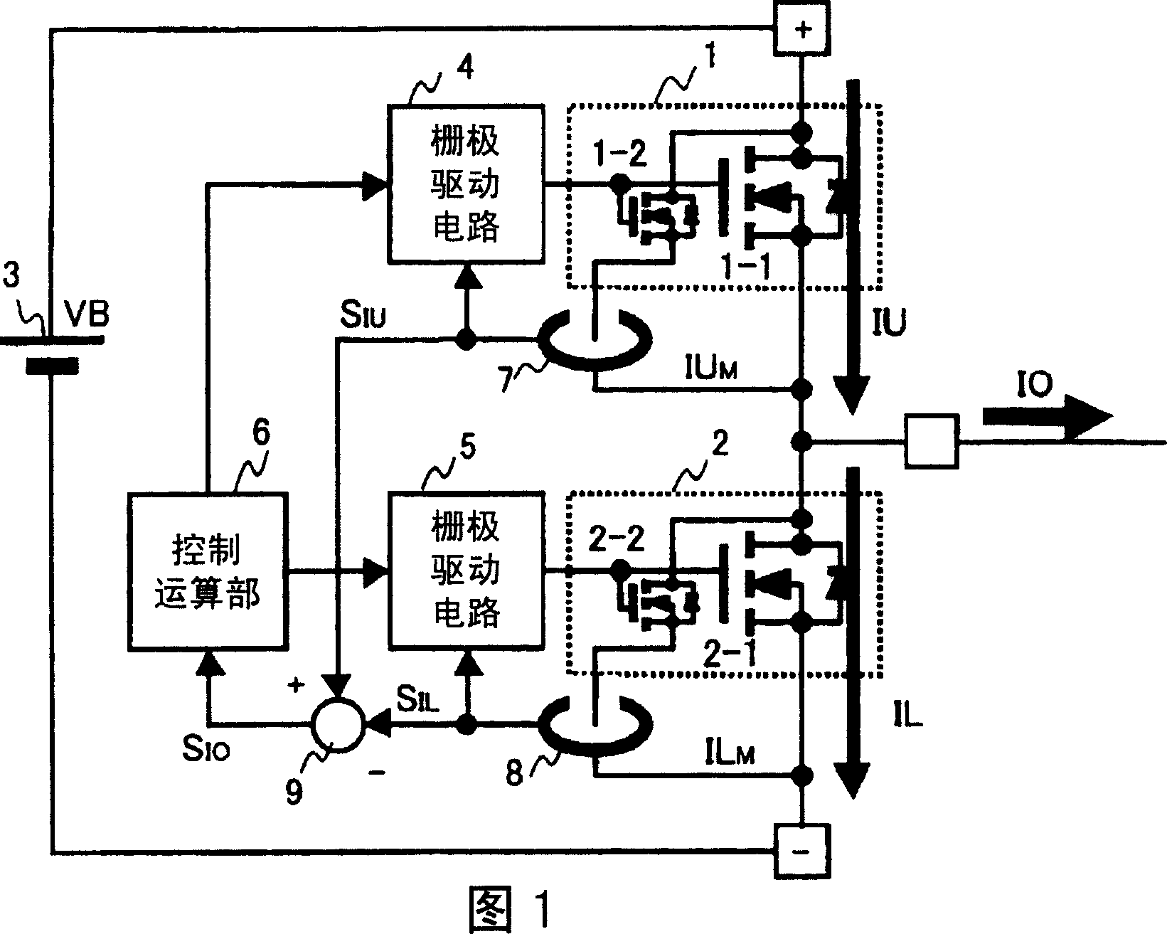
[0025] FIG. 1 shows Embodiment 1 of the present invention, which is an embodiment when the present invention is applied to, for example, an excitation chopper circuit or a switching circuit used in a motor control device disclosed in Patent Document 2 mentioned above.

[0026] Furthermore, as shown in the figure, in the first embodiment, the switching element 1 serving as the upper arm and the switching element 2 serving as the lower arm are connected in series between the + terminal and the - terminal to which the DC voltage VB is applied from the DC power supply 3 , Currents IU and IL flowing to the respective elements are switched, and an output current IO is supplied from an output terminal O to a load (not shown) such as a motor.

[0027] For this reason, each switching element 1, 2 is equipped with a gate drive circuit 4, 5 respectively, and is respectively switched and controlled under the control of the control calculation unit 6. If the switching timing and switching ...

Embodiment approach 2

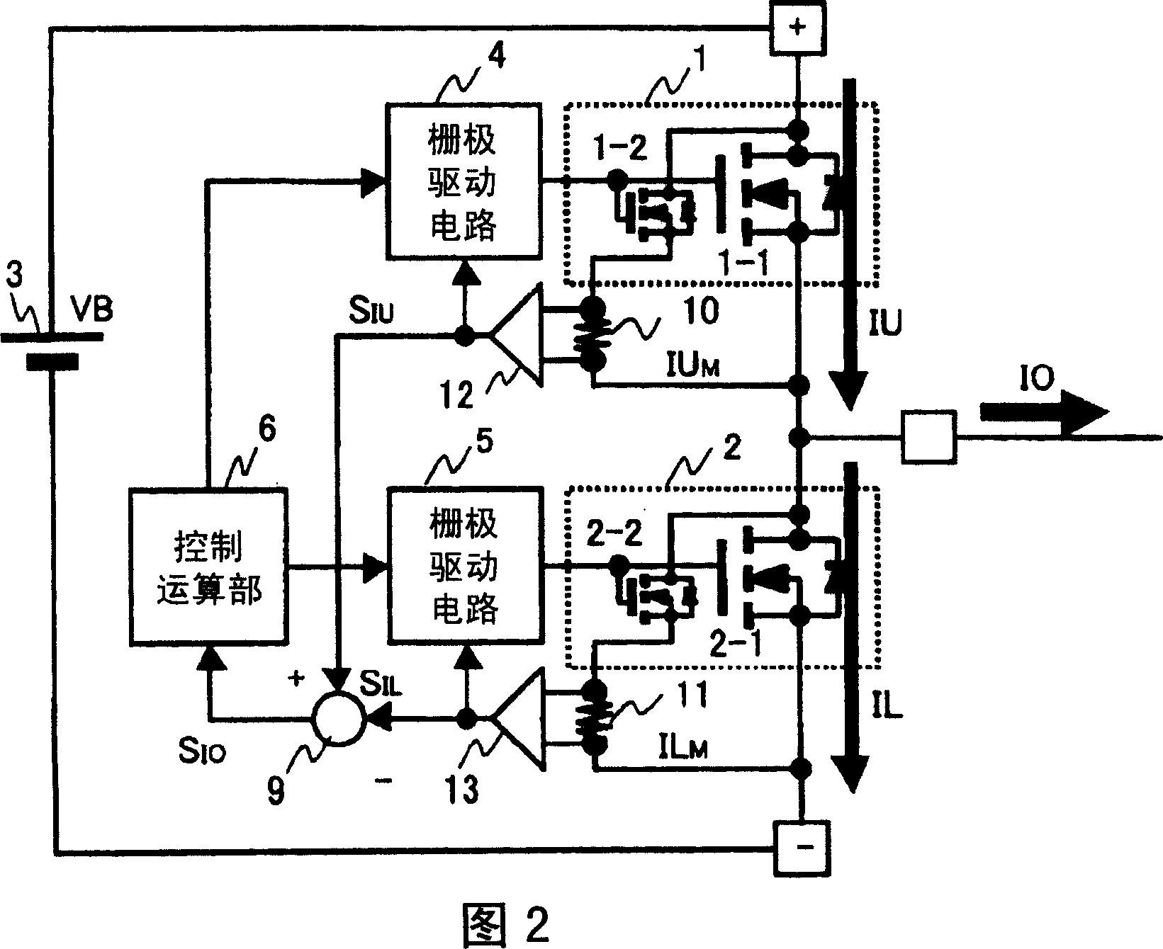
[0042] Next, Embodiment 2 of the present invention will be described based on FIG. 2 . Here, this Embodiment 2 is an embodiment of the present invention when the Miller current is detected by the shunt resistance. For this purpose, shunt resistances 10, 11 are inserted into the respective Miller elements 1-1, 2 as shown in the figure. -2 current paths, differential circuits 12 and 13 are connected in parallel to them, and other constituent elements are the same as those of Embodiment 1 shown in FIG. 1 .

[0043] First, the shunt resistor 10 generates the Miller current IU based on the Miller element 1-2 M The differential circuit 12 operates as follows: the voltage drop is detected to obtain a detection signal S indicating the current IU flowing in the switching element 1 of the upper arm. IU , on the other hand, the shunt resistor 11 produces the Miller current IL based on the Miller element 2-2 M The differential circuit 13 operates as follows: the voltage drop is detected...

Embodiment approach 3

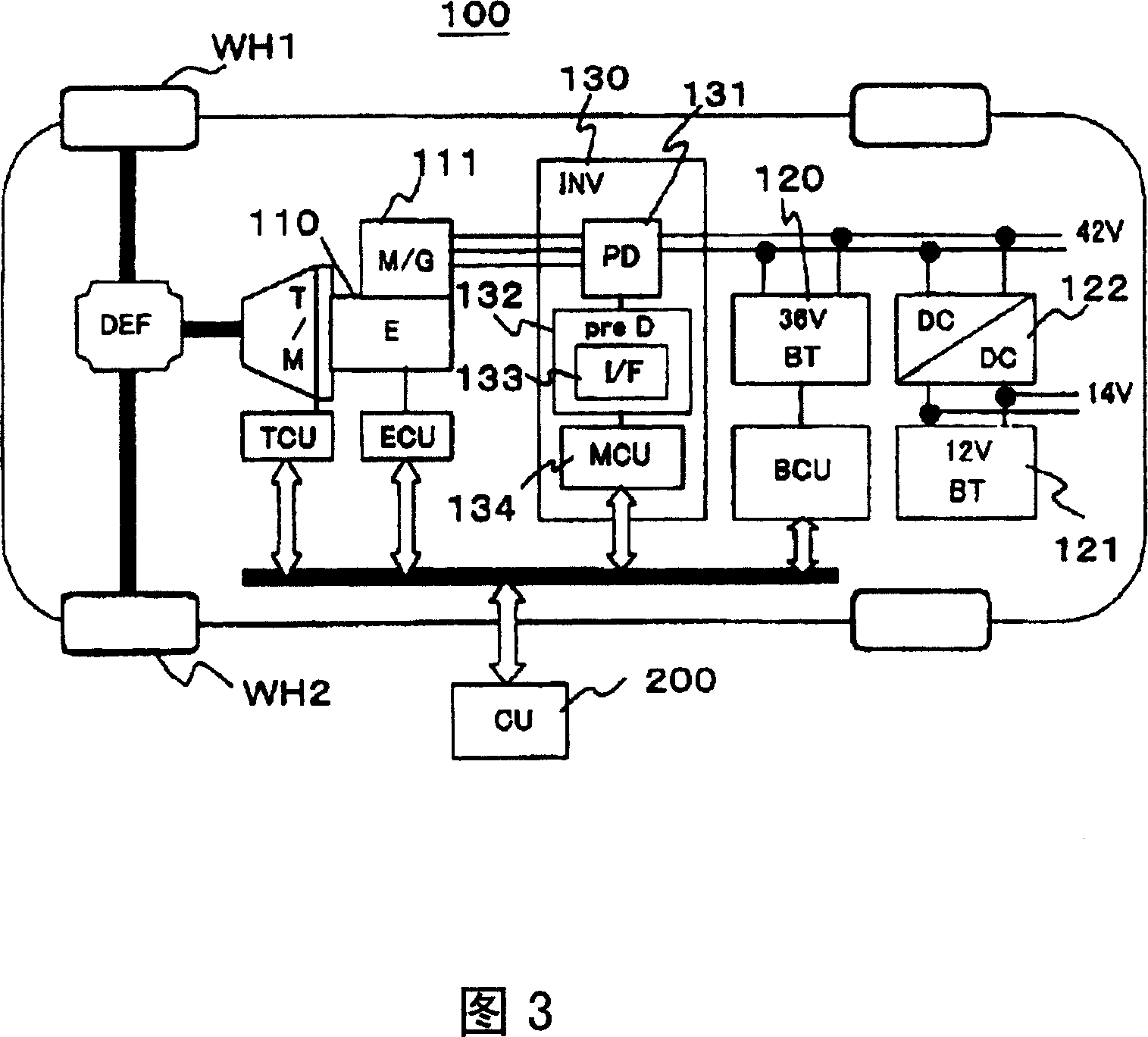
[0051] Next, as Embodiment 3, a vehicle equipped with a power conversion device according to the present invention will be described with reference to FIG. 4 . Here, the vehicle according to Embodiment 3 is shown as an automobile 100 , and uses, for example, an engine 110 such as a gasoline engine as a power source.

[0052] Moreover, when the automobile 100 is running, the torque of the engine 110 is transmitted to the wheels WH1 and WH2 through the transmission (transmission) device T / M and the differential gear device DEF. At this time, the engine 110 and the M / G (generator) The 111 connection makes the M / G 111 operate not only as a normal alternator but also as a starter for the electric motor 110 .

[0053] Therefore, the M / G 111 operates as an alternator while the engine 110 is rotating, and charges the two secondary batteries, the main battery 120 with a terminal voltage of 36V and the auxiliary battery 121 with a terminal voltage of 12V, and the engine 110 At the time...


PUM


Abstract

A power conversion device is provided. Switching elements are connected in series, currents IU and IL flowing in respective elements are switched, and an output current IO is supplied to a load, such as a motor, from an output terminal O. In this case, a MOSFET having a mirror element, where mirror elements are provided in main switching elements, is used as the switching elements; current detection circuits are provided in respective mirror elements each; the current detection circuits extract mirror currents IU, IL flowing in the mirror elements as detection signals S< IU>, S; the detection signals are inputted into a comparison circuit 9 as a difference signal S of the detection signals S, S; the difference signal is input to a control operation section 6 as a signal indicating the output current IO; and the switching timing of the switching elements and switching time are controlled. Therefore, a compact, low-loss, and low-cost power conversion device for detecting current is provided, where there is no risk of restriction on output voltage performance.

Description

technical field [0001] The present invention relates to a power conversion device with an output current detection function, in particular to a power conversion device suitable for a servo system, a DC / DC converter or a three-phase AC inverter. Background technique [0002] It is common practice to detect the output current for the control of power conversion devices such as servo systems, DC / DC converters, or three-phase AC inverters, and various current sensors have been proposed. (core) insulated current sensor is the so-called Hall sensor. Here, the Hall sensor means that a conductor through which the current to be measured is passed through a ring-shaped magnetic core, and the Hall sensor installed on the magnetic circuit of the magnetic core reads the magnetic field generated by the current and detects it as a current. [0003] In addition, in addition to the Hall sensor, there is also known a shunt resistance type current sensor in which a shunt resistance is inserte...

Claims


Application Information

Patent Timeline
Patent Type & Authority Applications(China)
IPC IPC(8): H02M7/48H02M7/5387
CPCH03K17/0822H02M2001/0009H03K17/6871H02M1/0009
Inventor 重田哲藤野伸一桥元庆太濑户贞至
Owner HITACHI LTD
Why Eureka
Try Eureka