Al technical title is built by PatSnap Al team. It summarizes the technical point description of the patent document.
A technology of installation device and tolerance compensation, which is applied in the direction of connecting components, threaded fasteners, thin plate connections, etc., and can solve problems such as unsightly dividing lines and small glove boxes
Inactive Publication Date: 2007-09-12
NISSAN MOTOR CO LTD
View PDF1 Cites 22 Cited by
Summary
Abstract
Description
Claims
Application Information
AI Technical Summary
This helps you quickly interpret patents by identifying the three key elements:
Problems solved by technology
Method used
Benefits of technology
Problems solved by technology
Unfortunately, this structural requirement adds additional constraints to the design of the cockpit components, such as possible smaller glove boxes or unsightly dividing lines, etc.
Method used
Image
Click on the blue label to locate the original text in one second.
Reading with bidirectional positioning of images and text.
Examples
Embodiment Construction
[0023] Selected embodiments of the invention will now be described with reference to the drawings. Those skilled in the art to which the present invention belongs can find out from the content disclosed in the present invention that the following descriptions of the embodiments of the present invention are only for illustration, rather than for the purpose of limiting the present invention, and the present invention is defined by the appended claims book and its equivalents.
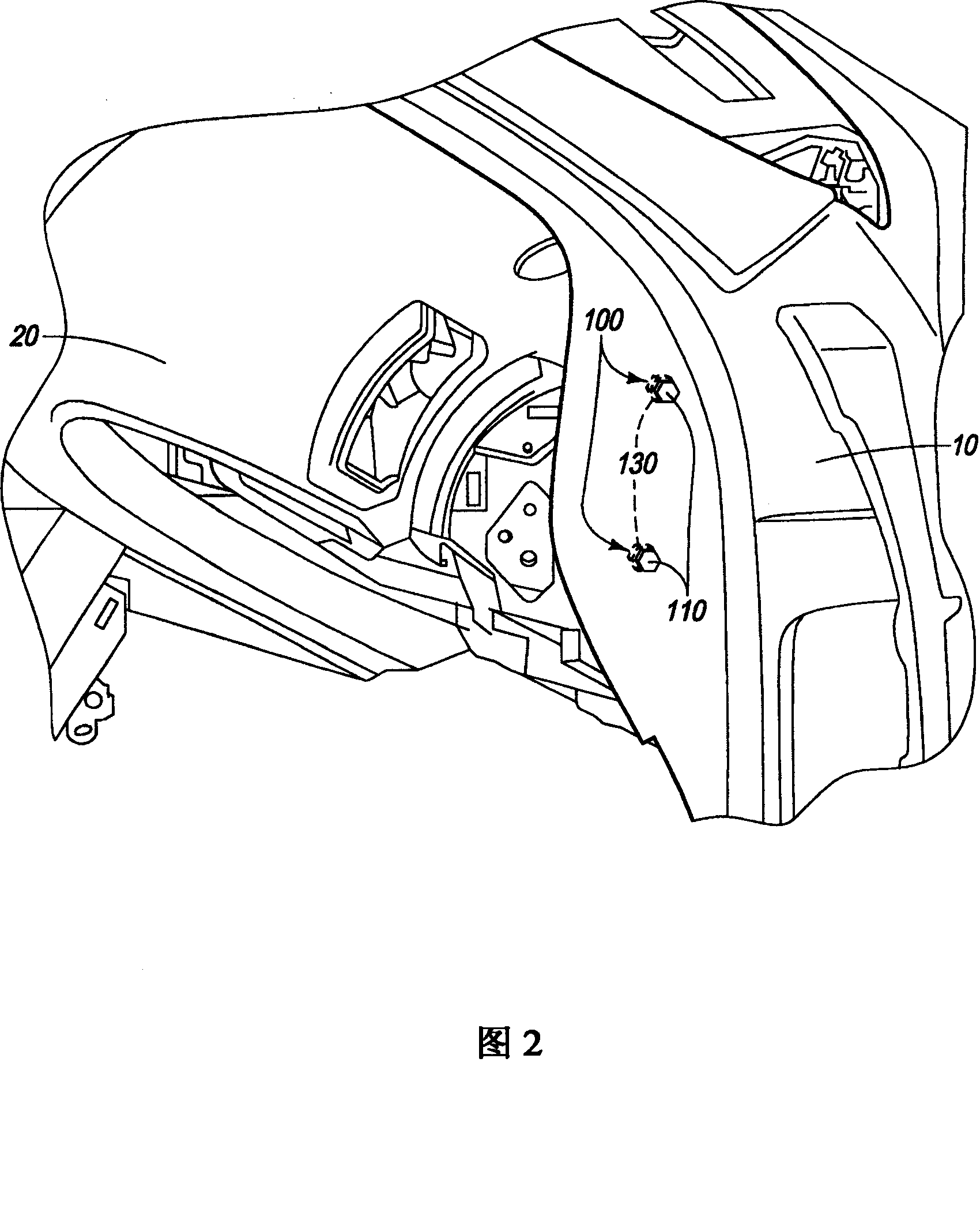
[0024] FIG. 1 is a side view of a vehicle V including a vehicle body 10 . FIG. 2 is a rear perspective view of the front portion of the passenger compartment of the vehicle V on the passenger seat side, showing the vehicle body 10 connected to the instrument panel 20 . FIG. 3 is a rear perspective view of the instrument panel 20 showing the mounted state of the vehicle body 10 before being mounted on the instrument panel. As shown in FIG. 2, in the cockpit assembly of the vehicle V, the instrument pane...
PUM
Abstract
A tolerance compensating mounting device (100, 100') has a threaded fastener (110, 110'), an outer member (120, 120') including a mounting bore, and a tubular member (130, 130', 230, 330, 430, 530, 630). The tubular member (130, 130', 230, 330, 430, 530, 630) has an internal surface (132a, 132a') rotatably coupled to the threaded fastener (110, 110') and an external surface (134a, 134a') rotatably coupled within the mounting bore of the outer member (120, 120') such that the tubular member (130, 130', 230, 330, 430, 530, 630) rotates about a center axis of the tubular member (130, 130', 230, 330, 430, 530, 630) in synchronization with rotation of the threaded fastener (110, 110') to move with respect to the outer member (120, 120') in a direction protruding from the outer member (120, 120') and then the threaded fastener (110, 110') subsequently rotates with respect to the tubular member (130, 130', 230, 330, 430, 530, 630) upon further rotation of the threaded fastener (110, 110'). The tubular member (130, 130', 230, 330, 430, 530, 630) has a tool engaging structure (138, 138', 238, 338, 438, 538, 638) formed on an axial end surface of the tubular member (130, 130', 230, 330, 430, 530, 630) at a first axial end portion with the tool engaging structure (138, 138', 238, 338, 438, 538, 638) being radially spaced between the external surface (134a, 134a') and the internal surface (132a, 132a') of the tubular member (130, 130', 230, 330, 430, 530, 630).
Description
technical field [0001] The present invention generally relates to a tolerance compensating mounting device for compensating for clearance tolerances formed between a vehicle component and a vehicle body while mounting the vehicle component on the vehicle body. Background technique [0002] Many interior components of a conventional motor vehicle are connected together and / or to the body of the vehicle by threaded fasteners. From an aesthetic point of view, it is desirable to have interior components fit together without play. However, from a manufacturing point of view, the cost of fitting the interior components together without play is very high. Accordingly, tolerance compensating mounting devices have been developed to adjust the clearance between vehicle interior components and / or between vehicle interior components and the vehicle body. An example of a conventional tolerance compensating mounting arrangement is disclosed in US Patent No. 6,884,014. This patent discl...
Claims
Application Information
Patent Timeline
Application Date:The date an application was filed.
Publication Date:The date a patent or application was officially published.
First Publication Date:The earliest publication date of a patent with the same application number.
Issue Date:Publication date of the patent grant document.
PCT Entry Date:The Entry date of PCT National Phase.
Estimated Expiry Date:The statutory expiry date of a patent right according to the Patent Law, and it is the longest term of protection that the patent right can achieve without the termination of the patent right due to other reasons(Term extension factor has been taken into account ).
Invalid Date:Actual expiry date is based on effective date or publication date of legal transaction data of invalid patent.