
High-altitude float platform

A floating platform and platform technology, applied in the field of platforms and high-altitude floating platforms, can solve the problems of high comprehensive use cost, narrow use range, limited load capacity, etc., and achieve the effects of low cost, strong wind resistance and reasonable structure.

Inactive Publication Date: 2007-09-05
王旭东
View PDF0 Cites 11 Cited by
  • Summary
  • Abstract
  • Description
  • Claims
  • Application Information

AI Technical Summary

Problems solved by technology

[0002] At present, the existing buoyancy aircraft mainly include airships and balloons. The former has a complex structure, is bulky, is not suitable for operation, is greatly affected by the wind, is easily damaged, and has a high overall cost of use; the latter has a single function and a limited load capacity. narrow range

Method used


Image

  • High-altitude float platform
  • High-altitude float platform

Examples


Embodiment Construction

[0010] In order to better understand the present invention, it will be further described in detail below with reference to the accompanying drawings and embodiments.

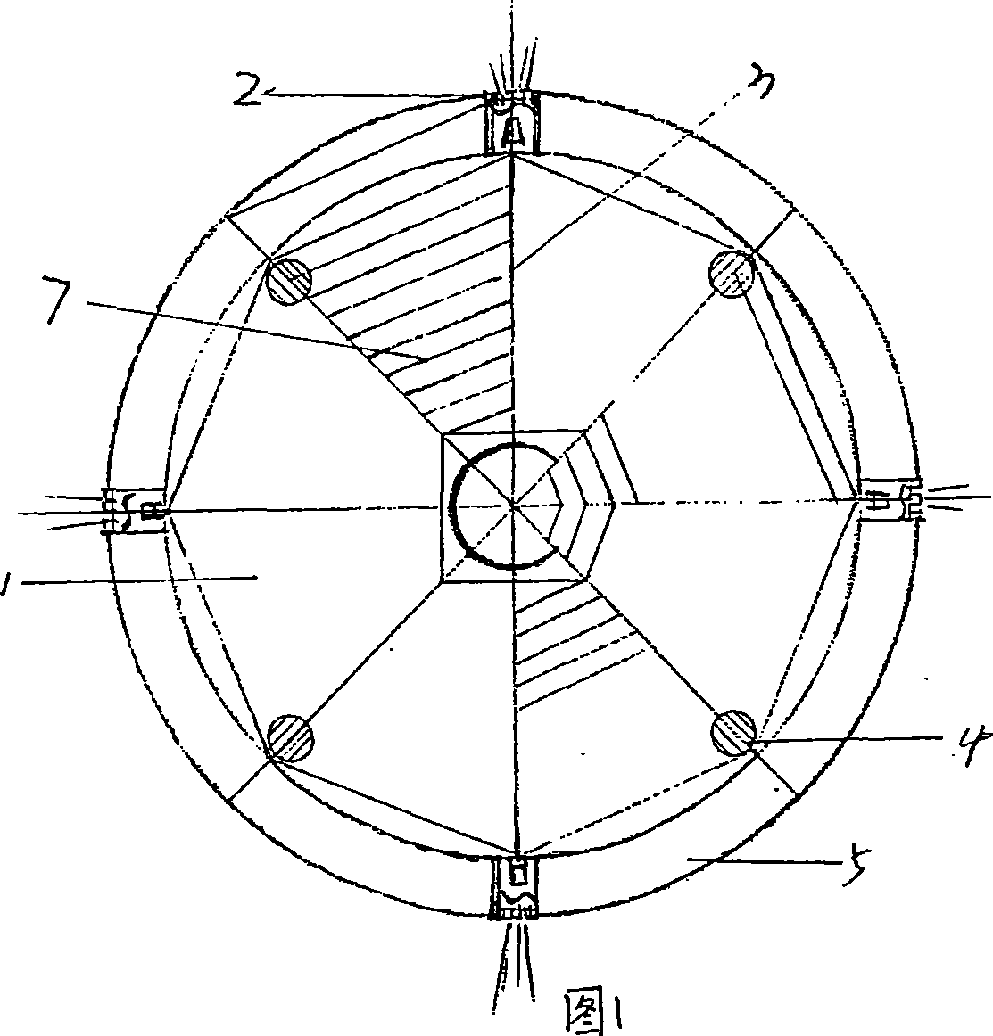
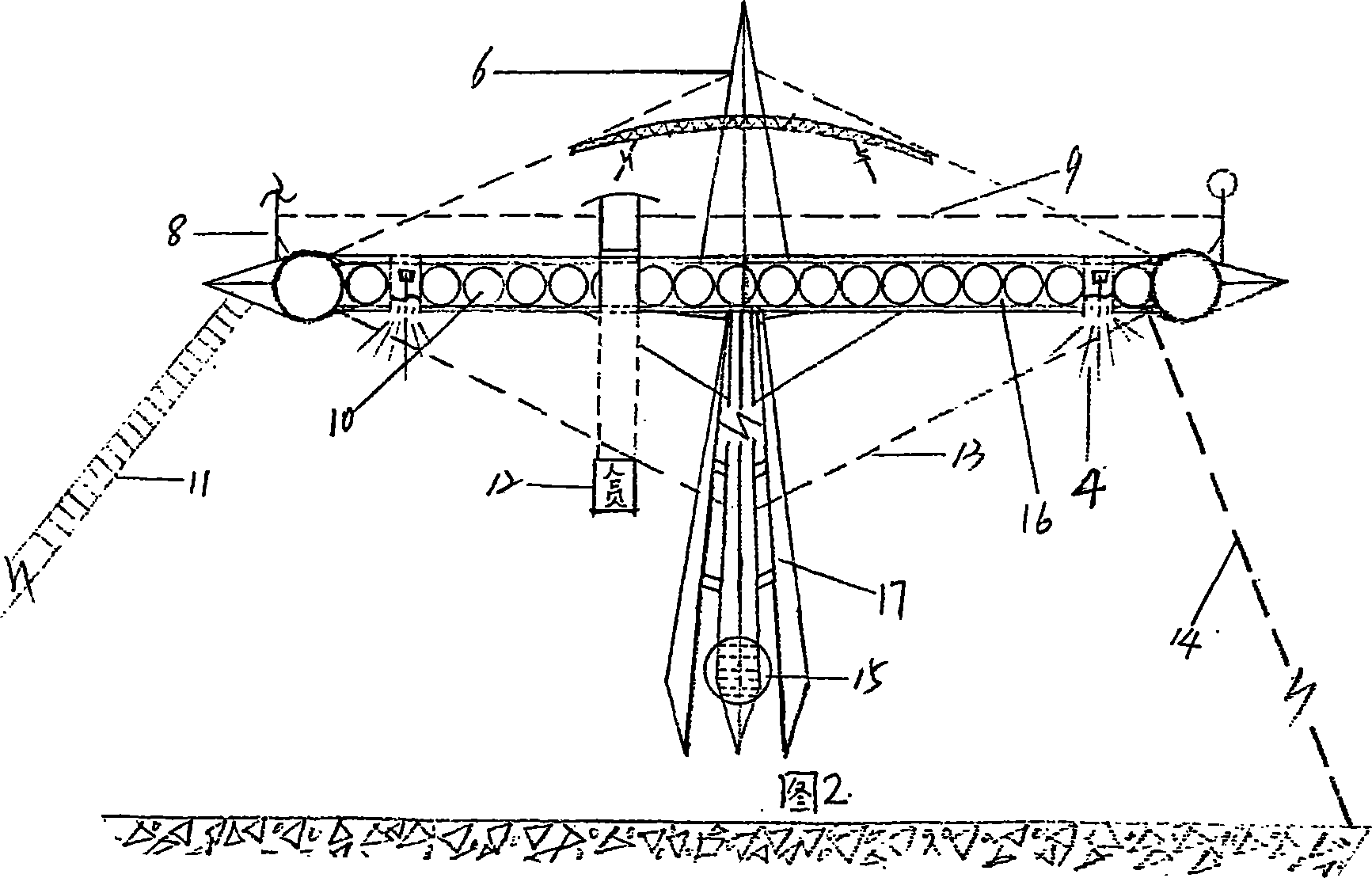
[0011] Figures 1 and 2 show a specific structural form of the platform. The high-altitude floating platform is mainly composed of a platform body 1 mounted on a lower bracket 17. A balance weight device 15 is provided on the bracket 17, and the platform There is an upper tower 6 above the body. Several tension wires 13 are connected between the platform body and the support and the upper tower to enhance the stability of the platform. The platform and the ground are connected by a number of mooring lines 14. In order to control the aerial attitude of the floating platform within an effective range; a cavity 16 is provided inside the platform body 1, and the cavity 16 is provided with independent tubular airbags 10 distributed in a row of tubes. A ring-shaped airbag 5 is provided on the periphery, and four cascade fa...


PUM


Abstract

A platform floating overhead is composed of a platform body on supporting frame, vertical tower on said platform body, several pull strings between them, several fixing cables between platform and ground, a ring air bag surrounding said platform body, several tubular air bags arranged in the cavities in platform body, the drive unit, the electric units, and several reinforcing ribs.

Description

1. Technical Field [0001] The invention discloses a platform, in particular a high-altitude floating platform that can be suspended in the high air and can be moved up and down at will, belonging to the technical field of buoyancy-type aerial vehicles. 2. Background technology [0002] At present, the existing buoyancy-type aircraft mainly include airships and balloons. The former has a complex structure, is bulky, is not suitable for operation, is affected by wind, is easily damaged, and has a high comprehensive use cost; the latter has a single function, limited load capacity, and use The range is narrow. Third, the content of the invention [0003] The purpose of the present invention is to overcome the above shortcomings of the prior art and provide a high-altitude floating platform with novel and unique structure, safe and reliable performance, and wide application range. [0004] In order to achieve the above objectives, the present invention is achieved as follows: a high...

Claims


Application Information

Patent Timeline
IPC IPC(8): B64B1/00
Inventor 王旭东
Owner 王旭东
Learn More