
Lock head device

A lock head and lock cylinder technology, which is used in construction locks, cylinder pin locks, locks with turning keys, etc., can solve the problems of high mutual opening rate, failure to achieve anti-theft effect, loss of anti-theft performance, etc., and achieve the manufacturing process. Simple and safe effect

Inactive Publication Date: 2007-08-15
邵文武
View PDF0 Cites 6 Cited by
  • Summary
  • Abstract
  • Description
  • Claims
  • Application Information

AI Technical Summary

Problems solved by technology

The mutual opening rate of this traditional lockset is very high, usually the mutual opening rate of the lock is 1 / 2000, and more importantly, this traditional lockset is easy to be used by thieves with unlocking tools (such as screwdrivers, special iron wires or other special tools). tools, etc.) to open it in a very short time, making it lose the anti-theft performance
The second type is the more popular atomic lock in the market. This kind of lock also has a circular bead structure, but it has some differences from the traditional upper and lower bead locks, that is, it improves the locking principle of internal pressure or external pressure edge block. This type of lock When it was first put on the market, it was also recognized by consumers. However, after using it for a long time, thieves became more and more familiar with the structure of this type of lock. It is produced at different positions of the round beads, and the round beads are the same as the traditional upper and lower bead locks. When opening, the round bead moves up and down to lock the side block. This principle is most handy for thieves to unlock.
However, due to the limitation of its structure, the atomic lock is usually a single-row bead structure, so the mutual opening rate is relatively high.

Method used


Image

  • Lock head device
  • Lock head device
  • Lock head device

Examples


Embodiment 1

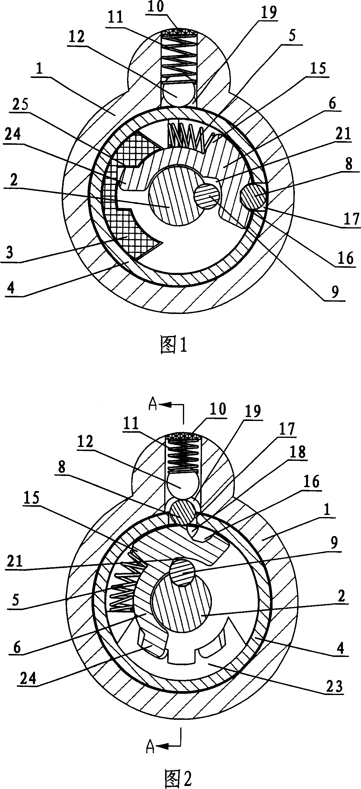
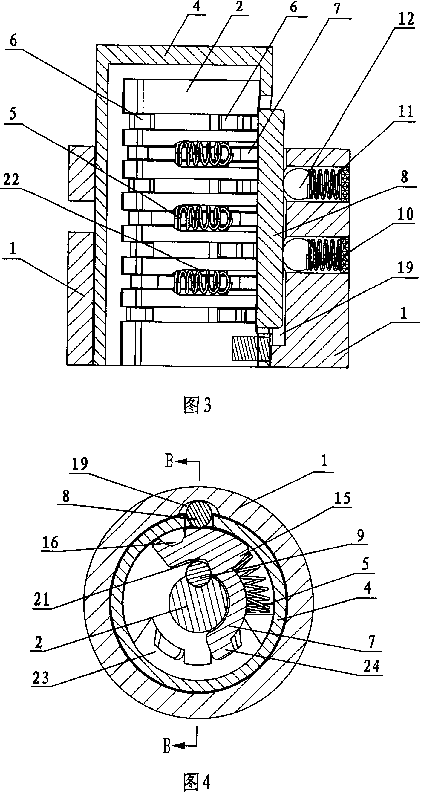
[0017] As shown in the figure: a lock head device of the present invention comprises a lock housing 1, a cylindrical middle housing 4 in the lock housing 1, a cylindrical lock core 2 in the middle housing 4, and the outer surface of the lock core 2 is provided with multiple The strip is perpendicular to the annular groove 13 of the central axis of the lock cylinder 2, and the surface of the lock cylinder 2 has a lock cylinder edge retainer groove 18 parallel to the axial direction of the lock cylinder 2, and the lock cylinder edge retainer groove 18 is located in the middle of the surface of the annular groove 13 , The middle shell 4 and the corresponding position of the lock shell 1 are respectively provided with a middle shell side stop groove 17 and a lock shell groove 19, and a cylindrical side stop 8 is arranged therein.

[0018] Each annular groove 13 is provided with an arc-shaped leaf 6, 7 and a leaf spring 5, and the leaf 6, 7 includes a left leaf 6 and a right leaf 7,...

Embodiment 2

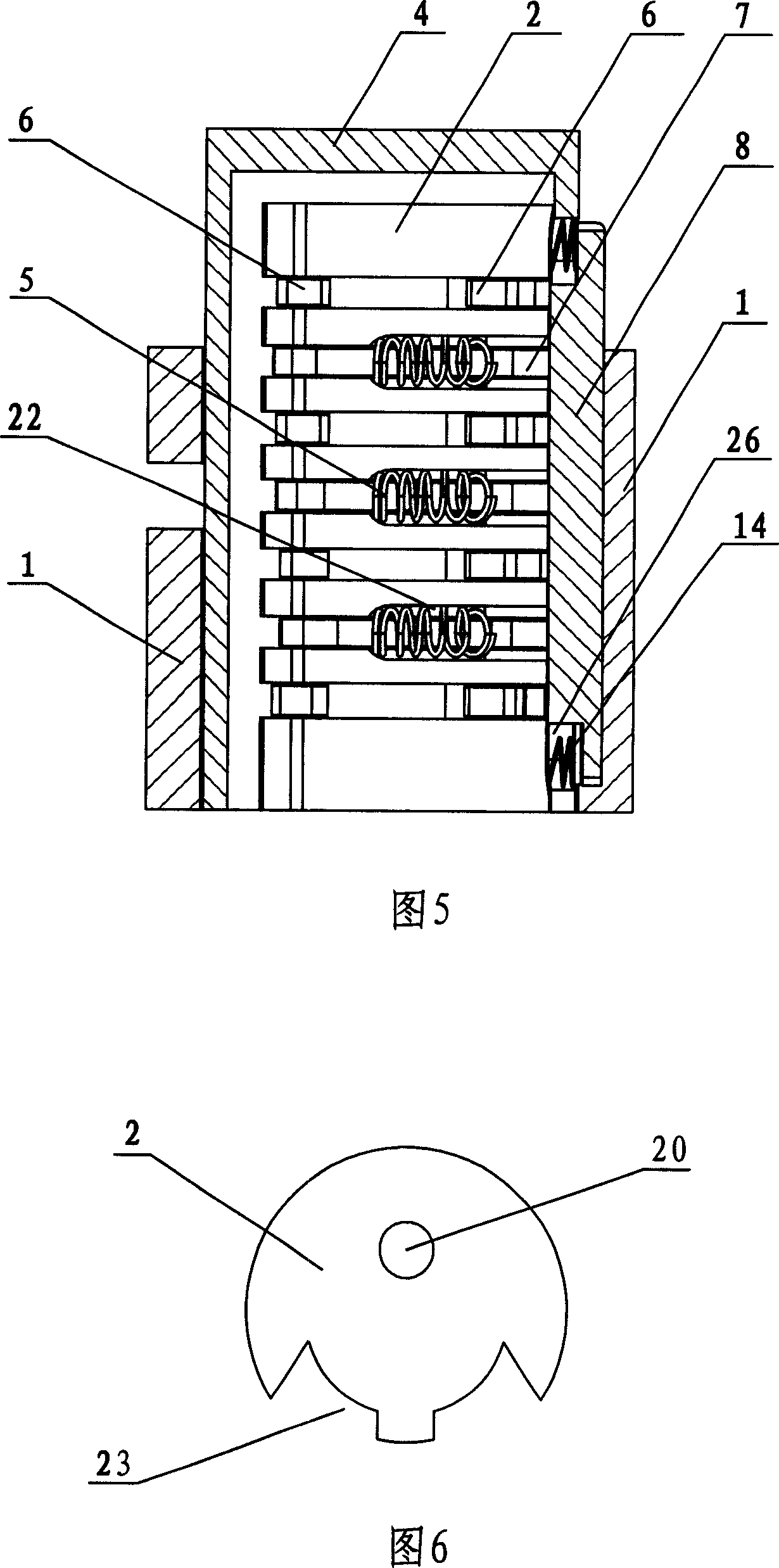
[0024] As shown in Fig. 4 and Fig. 5: a lock head device of the present invention includes a lock case 1, a cylindrical middle case 4 inside the lock case 1, a cylindrical lock core 2 inside the middle case 4, and an outer body of the lock core 2. The surface is provided with a plurality of annular grooves 13 perpendicular to the central axis of the lock cylinder 2, and the surface of the lock cylinder 2 has a lock cylinder side stopper groove 18 parallel to the axial direction of the lock cylinder 2, and the lock cylinder side stopper groove 18 is located on the surface of the ring groove 13. At the middle position of the middle shell 4 and the corresponding position of the lock shell 1, a middle shell edge retainer groove 17 and a lock shell groove 19 are respectively provided. The edges of the lock shell groove 19 transition smoothly, and there is a cylindrical edge Baffle 8; each annular groove 13 is provided with an arc-shaped leaf 6,7 and a leaf spring 5, and said leaf 6,...


PUM


Abstract

The invention relates to a lock device comprising a lock shell, a middle circular cylindrical shell in the lock shell, a cylindrical lock core inside the middle shell, a plurality of annular grooves arranged on the out surface of the lock core, a lock core side bumper groove which is installed on the lock core surface of the annular groove, a middle shell side bumper groove and a lock shell groove which are separately installed on relative positions of the middle shell and the lock shell, a bumper inside the middle shell or the lock shell, an arc sheet and a leaf spring inside the annular groove, wherein one end of the leaf spring is contacted a flange of the sheet outer arc while another end is contacted the lock core. All the sheet outer arcs are equipped with sheet grooves which can position in a line as sheet tooth meeting key bits thereby putting the side bumper into the side bumper groove of the lock core sheet. The invention achieves an involution centrifugal construction for sheet installing via using the side bumper and the arc sheet and the sheet spring in the every annular groove, and not only has anti-theft and highly safety ability, but also is durable, simple, and convenience in operation.

Description

Technical field [0001] The invention relates to a mechanical lock, in particular to a lock head device. Background technique [0002] At present, there are various types of locks on the market, but no matter what kind of lock, in terms of its substantial structure, it can be roughly divided into two categories: one is composed of upper and lower beads, and the other is The upper bead and the lower bead are single round beads, and the size changes of the lower beads are arranged and combined. The number of permutations and combinations determines the mutual opening rate of the lock. The mutual opening rate of this traditional lockset is very high, usually the mutual opening rate of the lock is 1 / 2000, and more importantly, this traditional lockset is easy to be used by thieves with unlocking tools (such as screwdrivers, special iron wires or other special tools). tools, etc.) to open it in a very short period of time, making it lose its anti-theft performance. The second ty...

Claims


Application Information

Patent Timeline
Patent Type & Authority Applications(China)
IPC IPC(8): E05B29/04E05B19/00
Inventor 邵文武
Owner 邵文武
Learn More