Precise linear displacement apparatus

A linear displacement and precision technology, applied in the direction of electromechanical devices, mechanical energy control, electrical components, etc., can solve the problems of slow response speed, large radial swing, and inaccurate precision, and achieve fast response speed, avoid radial swing, and axis To move the effect of high precision

Active Publication Date: 2007-08-08
YIXING GUIXIN MAGNETOELECTRIC HI TECH
View PDF0 Cites 0 Cited by
  • Summary
  • Abstract
  • Description
  • Claims
  • Application Information

AI Technical Summary

Problems solved by technology

Using a permanent magnet motor as an input can provide a long-range displacement output, but the position positioning is not accurate enough and cannot be applied to some precision linear displacement applications; using a stepper motor as an input can provide a short-range more accurate displacement, but in general , there are many parts, the mechanism is complicated, and the volume is huge, so that errors will occur during the movement of the bearing seat, resulting in a state of inaccurate accuracy
In addition, large radial swing during motion, slow response speed, noise generated by mechanical transmission, loss caused by component friction, and poor resistance to bumps and impacts are all fatal flaws of the traditional structure, which largely limits its application in the field of precision linear displacement. Applications

Method used


Image

  • Precise linear displacement apparatus
  • Precise linear displacement apparatus
  • Precise linear displacement apparatus

Examples


Embodiment Construction

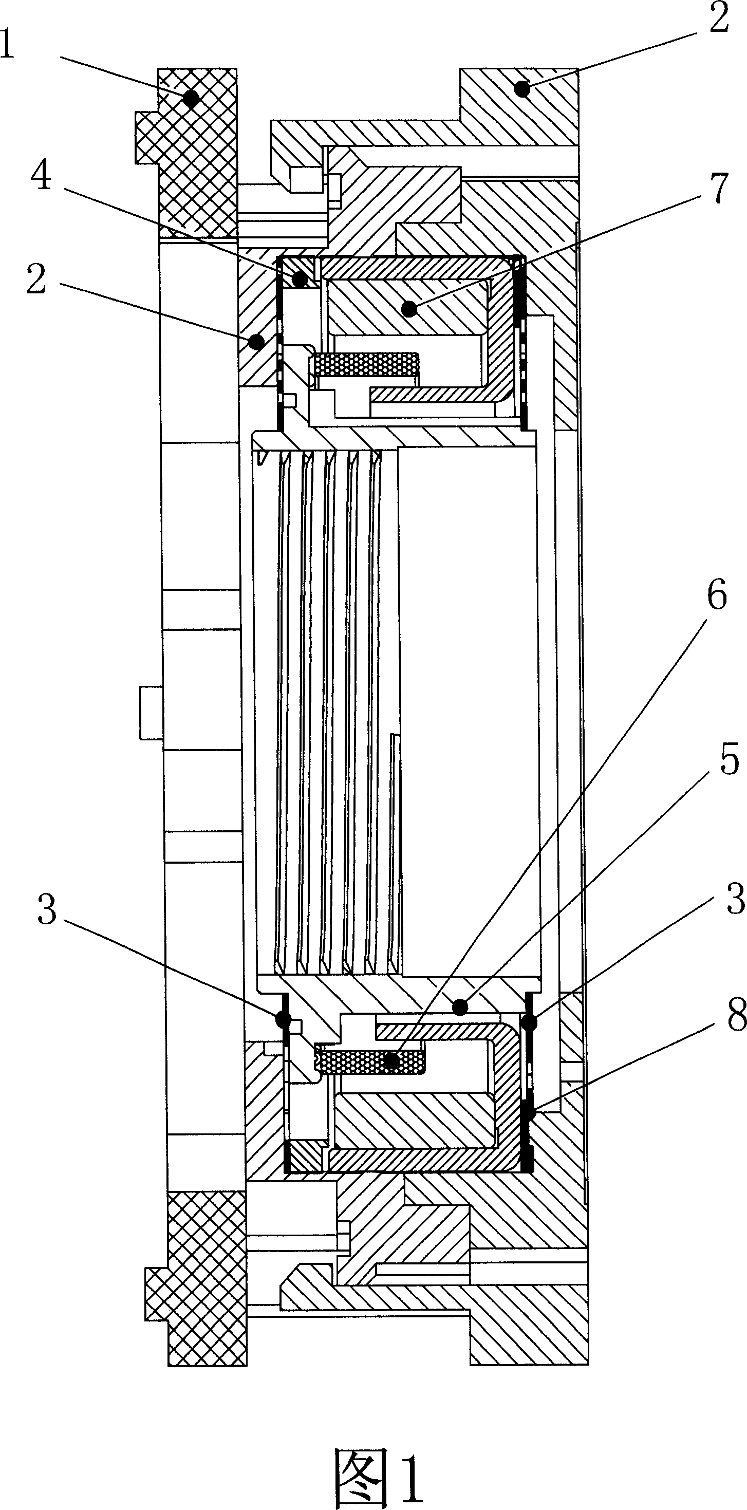
[0022] As shown in Figure 1, the present invention includes: a housing 2, a motion carrier 5, an electromagnetic drive unit 6, a permanent magnet unit 7 and an elastic support seat 3, the permanent magnet unit 7 is arranged in the housing 2, and the motion carrier 5 passes through The elastic support seat 3 is installed in the housing 2, and the electromagnetic drive unit 6 is fixed on the motion carrier 5. When the electromagnetic drive unit 6 is energized, the permanent magnet unit 7 applies a moving load to the electromagnetic drive unit 6 with the elastic support seat 3. The seat 5 acts oppositely, and the electromagnetic drive unit 6 drives the motion carrier 5 to move under the action of the permanent magnet unit 7 .

[0023] The specific embodiments of the present invention will be described below with the aid of the accompanying drawings, in which similar or identical parts are denoted by the same reference numerals.

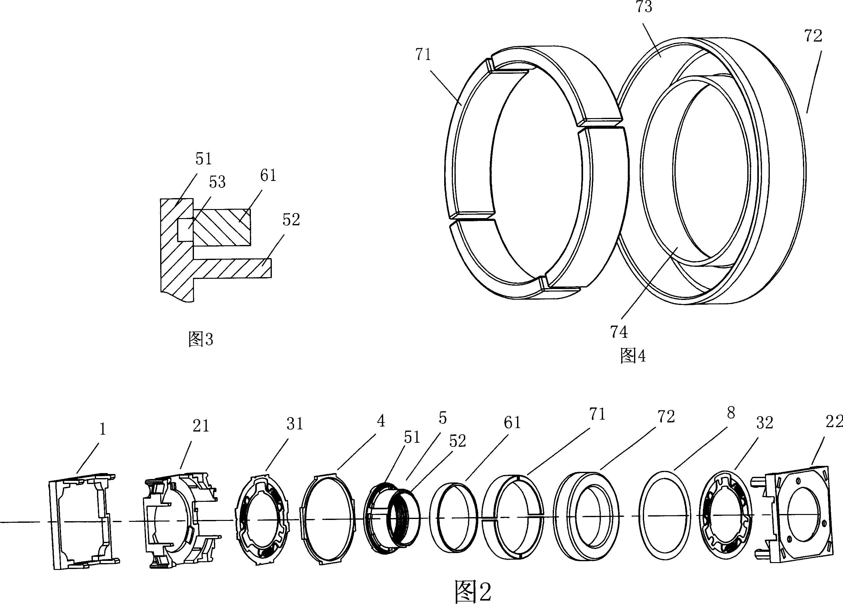
[0024] As shown in Figures 1 and 2, the electromag...


PUM


Abstract

The invention relates to one fine displacement device, which comprises shell, move load socket, electrical magnetic drive unit, permanent unit and spring socket, wherein, the permanent magnetic unit is set inside shell; the move load socket is fixed inside shell through spring supportive socket; electrical magnetic drive unit is fixed on move socket; when electrifying the drive unit, permanent unit exerts the reverse force on the socket to drive the said move socket.

Description

technical field [0001] The invention relates to a precision linear displacement device, in particular to the application field of precision short-range linear displacement for micro-head reading and writing systems, medical detection imaging systems, image adjustment systems, micro-robot drives, micro-switches and micro-fluid pumps. Background technique [0002] For now, common linear displacement devices are usually composed of permanent magnet motor or stepper motor input, mechanical transmission mechanism and output bearing mechanism. Figure 10 is a schematic structural diagram of a traditional typical linear displacement device. Please refer to Figure 10, the current technology linear displacement device CTZZ includes: input motor (permanent magnet or stepper) CT01, feed screw (worm) CT03, nut CT04 matching the feed screw, and linear displacement bearing seat CT05 fixed on this nut. When the rotating shaft end of the input motor CT01 is inserted into the gear CT02 and t...

Claims


Application Information

Patent Timeline
IPC IPC(8): H02K33/18H02K7/14
Inventor 邵柏芝臧庆龙
Owner YIXING GUIXIN MAGNETOELECTRIC HI TECH
Why Eureka
Try Eureka