
Exposure control method, exposure control apparatus, and image pickup apparatus

An image pickup device and exposure value technology, which is applied in the direction of image communication, TV, color TV parts, etc., can solve the problems of complex image imaging device system, inability to pick up moving images, and difficulty in detecting flicker components

Inactive Publication Date: 2007-08-01
SONY CORP
View PDF7 Cites 50 Cited by
  • Summary
  • Abstract
  • Description
  • Claims
  • Application Information

AI Technical Summary

Problems solved by technology

[0028] However, the methods described in Patent Documents 1 and 2 to estimate the flicker component by measuring the light quantity of a fluorescent lamp using a light receiving element or a light measuring element increase the cost of the image pickup device by adding a light receiving element or a light measuring element to the image pickup device. System Size and Cost
[0029] The method of picking up two different types of images under two different shutter conditions and estimating flicker components described in Patent Document 3 also has the disadvantage of complicating the system of the image forming device
In addition, this method has the defect that it is not suitable for picking up moving images
[0030] The method of using the preparatory coefficients stored in the memory as the correction signal described in Patent Document 4 has the disadvantage that it is impossible to reliably detect and reduce flicker according to the fluorescent lamp type since it is impossible to prepare the correction coefficients for all types of fluorescent lamps weight
In addition, regarding the method of extracting the flicker component from the video signal using the frequency difference between the video signal component and the flicker component of Patent Document 4, in the black background portion and the low-brightness portion where the flicker component is very small in the image, the flicker component is combined with The video signal components are different, it is difficult to detect the flicker component, and the performance of detecting the flicker component is significantly reduced when one or more moving objects are present in the image
[0031] Finally, like the method described in Patent Document 3, the method of picking up two different types of images at different times to estimate flicker components described in Patent Document 5 complicates the system of the image pickup device and is not suitable for picking up moving images

Method used


Image

  • Exposure control method, exposure control apparatus, and image pickup apparatus
  • Exposure control method, exposure control apparatus, and image pickup apparatus
  • Exposure control method, exposure control apparatus, and image pickup apparatus

Examples


Embodiment Construction

[0081] Embodiments of the present invention will now be described in more detail with reference to the accompanying drawings. It should be understood that the present invention is not limited to the following examples, and various modifications can be made without departing from the spirit and scope of the present invention.

[0082] FIG. 7 is a schematic block diagram of a video camera 100 realized by applying an embodiment of the present invention, and illustrates its configuration.

[0083] In other words, FIG. 7 is a schematic block diagram of an image pickup device according to an embodiment of the present invention, and shows a configuration therein, which is a camera 100 using a CMOS imaging element 12 as an XY address scanning type imaging element.

[0084] With the video camera 100 , light from a subject enters the CMOS imaging element 12 through the imaging optical system 11 and undergoes photoelectric conversion in the CMOS imaging element 12 to obtain an analog vid...


PUM


Abstract

A technique of acquiring a width obtaining an appropriate exposure with minimum restrictions, while accurately correcting flickering is provided. An exposure control method includes integrating a video signal obtained by shooting a subject by means of a CMOS imaging element as input video signal over not less than a horizontal period, normalizing the integral value or the difference value of the integral value between neighboring fields or frames, extracting the integral value or the difference value after the normalization as flicker spectrum, determining, based on the extracted flicker spectrum, the presence or absence of a flicker component contained in the video signal obtained by the imaging element and controlling the exposure value, using a program diagram for preferentially employing the shutter speed less liable to produce flickering when it is determined that the video signal contains a flicker component.

Description

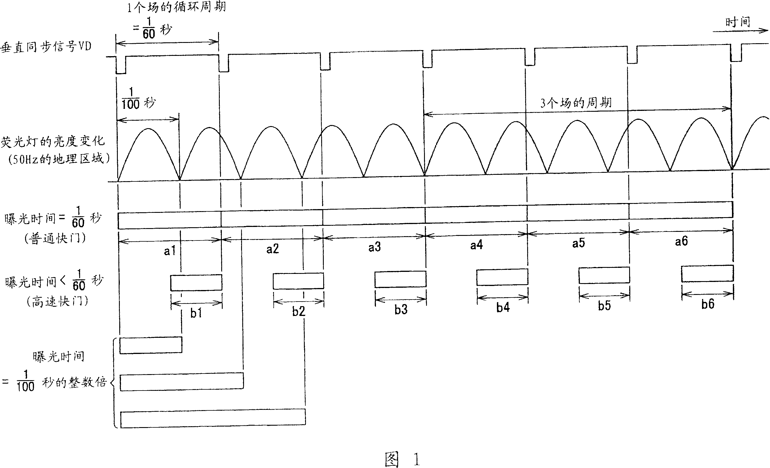
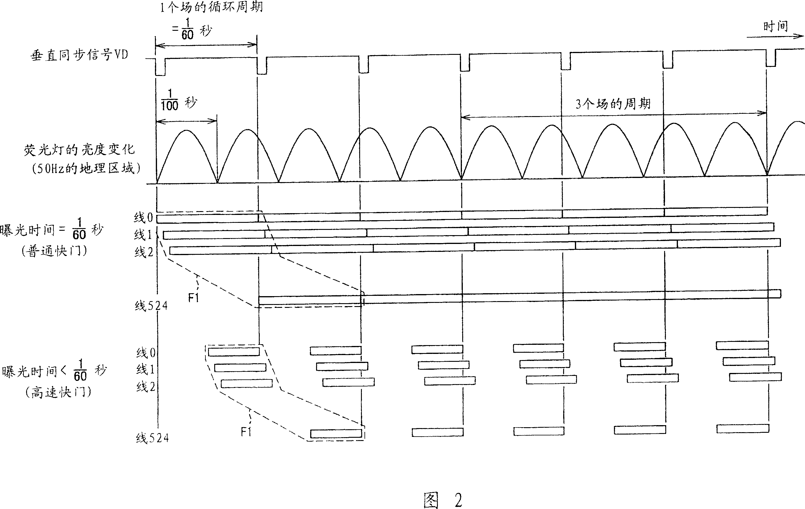
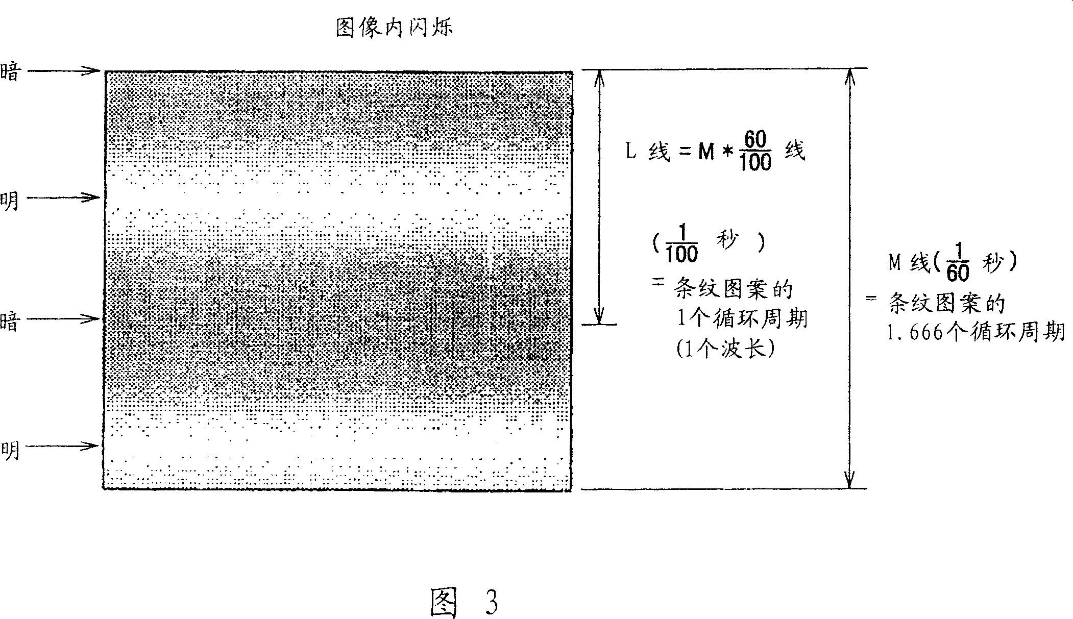
technical field [0001] The present invention relates to an exposure control method and exposure control apparatus under fluorescent lamp illumination used in an image pickup apparatus such as a video camera including an XY address scanning type imaging element (imager, imaging sensor) or In a digital camera, the imaging element is generally a CMOS (complementary metal oxide semiconductor) imaging element, and the present invention also relates to an image pickup device. Background technique [0002] When an image of a subject is picked up by a camera under direct light from a fluorescent lamp excited by a commercial AC power source, since the brightness change (light amount change) frequency of the fluorescent lamp (corresponding to twice the frequency of the commercial AC power source) is perpendicular to the camera The difference between the synchronization frequencies, a temporal fluctuation, or so-called flicker, occurs in the luminance of the video signal output as a re...

Claims


Application Information

Patent Timeline
Patent Type & Authority Applications(China)
IPC IPC(8): H04N3/15H04N5/335H04N5/243H04N23/76H04N25/00
CPCH04N5/2357H04N5/235H04N5/2353H04N23/70H04N23/745H04N23/73H04N23/741H04N23/76H04N23/71
Inventor 桐泽司
Owner SONY CORP
Learn More