LCD panel

A liquid crystal display and panel technology, applied in instruments, nonlinear optics, optics, etc., can solve the problems of liquid crystal pollution, uneven thickness of the liquid crystal screen, poor picture quality, etc., to ensure the uniformity of liquid crystal, improve the display effect, guarantee The effect of box thickness uniformity

Active Publication Date: 2010-02-03
K TRONICS (SUZHOU) TECH CO LTD +1
View PDF4 Cites 0 Cited by
  • Summary
  • Abstract
  • Description
  • Claims
  • Application Information

AI Technical Summary

Problems solved by technology

When the amount of liquid crystal is too much, when the liquid crystal is heated and expanded, or the liquid crystal at the edge of the pixel area is too much after the vacuum box is assembled, the liquid crystal 8 will be in contact with the sealing glue 4, such as figure 2 As shown, the interaction occurs under certain conditions, causing liquid crystal contamination
In addition, in the vacuum box, under the action of strong electrostatic adsorption and atmospheric pressure, the partial spacer and glass fiber behind the box will be deformed due to excessive force, making the LCD box thicker. Uniformity, resulting in edge Mura (a general term for poor picture quality) and other defects, which have varying degrees of impact on the display quality and yield of LCD screens

Method used


Image

  • LCD panel
  • LCD panel
  • LCD panel

Examples


Embodiment 1

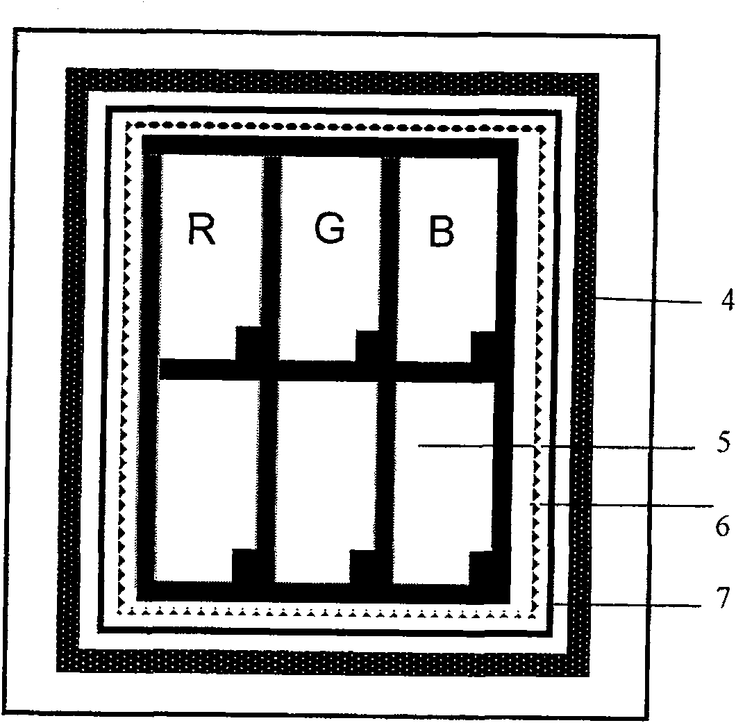
[0035] Figure 5 It is a schematic diagram of the implementation structure of the inner layer isolation frame in the specific embodiment 1 of the present invention. Such as Figure 5 As shown, in the present embodiment, a series of square grooves 10 of the inner layer isolation frame are formed on the inner layer isolation frame 6, the height of the inner layer isolation frame is H, and the depth of the square groove 10 of the inner layer isolation frame is 2 / 3H Left and right, the distance between the square grooves 10 of the inner layer isolating frame is W, and the width of the square groove of the inner layer isolating frame is about 1 / 3W. Image 6 It is a schematic diagram of the structure of the outer isolation frame proposed by the present invention. Such as Image 6 As shown, the heights of all positions of the outer layer isolation frame 7 are H.

[0036] Figure 7 It is a schematic diagram of the rear panel after adding the isolation frame and dropping the liqui...

Embodiment 2

[0039] Figure 9 It is a structural schematic diagram of an embodiment of the inner layer isolation frame in the specific embodiment 2 of the present invention. Such as Figure 9 As shown, the groove 6 structure of the inner layer isolation frame in this embodiment is different from the square structure in the specific embodiment 1, specifically, a series of inner layer isolation frame triangular grooves 11 are formed on the inner layer isolation frame 6, the The width and depth of the triangular groove 11 of the inner spacer frame can be set with reference to the width and depth in the specific embodiment, and the specific function of the triangular groove 11 of the inner layer spacer frame is the same as in the specific embodiment 1, and will not be described in detail.

Embodiment 3

[0041] Figure 10 It is a schematic diagram of the embodiment structure of the inner layer isolation frame in the specific embodiment 3 of the present invention. Such as Figure 9 As shown, the groove structure of the inner layer isolation frame in this embodiment is different from the square structure in the specific embodiment 1, specifically, a series of inner layer isolation frame trapezoidal grooves 12 are formed on the inner layer isolation frame 6, the inner layer isolation frame The width and depth of the trapezoidal groove 12 of the layer isolation frame can be set with reference to the width and depth in the specific embodiment, and the specific function of the trapezoidal groove 12 of the inner layer isolation frame is the same as that in the specific embodiment 1, and will not be described in detail.


PUM


Abstract

The present invention discloses a panel of a liquid crystal display device, which comprises a colorful film base panel and an array base panel which is arranged relatively; wherein, the thickness of abox between the colorful film base panel and the array base panel is kept by shock insulators; liquid crystal is filled between the colorful film base panel and the array base panel; a frame sealingglue which is arranged around the pixel areas of the colorful base panel and the array base panel seals the two base panels; wherein, an inner layer insulation frame and an outer layer insulation frame are arranged between the edges of the pixel areas and the frame sealing glue; one side or a plurality of sides of the inner layer insulation frame forms or form a series of grooves. Through arranging the insulation frame in the structure of two layers between the pixel areas and the sealing glue of the panel of the liquid crystal display device, the panel of the liquid crystal display device canprofitably control the quantity of the liquid crystal in the pixel areas, thereby avoiding the mutual function between the liquid crystal and the frame sealing glue. The thickness of the liquid crystal box is well stabilized, and further the display effect of the liquid crystal panel is improved.

Description

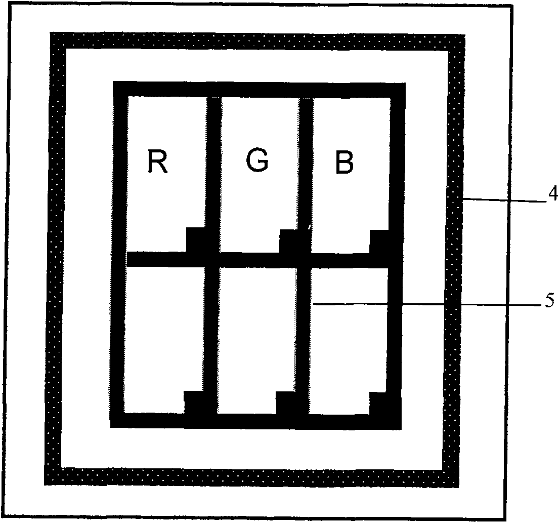
technical field [0001] The present invention relates to a liquid crystal display (TFT LCD), in particular to a panel of a liquid crystal display. Background technique [0002] Liquid crystal display (LCD) products have developed very rapidly in recent years, and its application fields are also constantly expanding. More and more high-quality LCD displays are gradually listed; at the same time, there are many problems, such as the interaction between liquid crystal and sealant. Liquid crystal contamination occurs, due to the uneven thickness of the pixel edge box, resulting in poor image quality when the LCD screen is displayed. [0003] figure 1 It is a schematic top view of the liquid crystal display panel structure in the prior art; figure 2 yes figure 1 Schematic cross-sectional view of the middle edge. Such as figure 1 with figure 2 As shown, the liquid crystal display panel in the prior art includes a color filter substrate 1 and an array substrate 2 arranged op...

Claims


Application Information

Patent Timeline
Patent Type & Authority Patents(China)
IPC IPC(8): G02F1/1362G02F1/1339
Inventor 李于华
Owner K TRONICS (SUZHOU) TECH CO LTD
Why Eureka
Try Eureka