


Quick Research
Generate reliable direction feasibility study reports for your R&D in just a few steps.

Technical Q&A
Discover and master advanced knowledge NOW. Basics, ideas, possibilities, all at once.

Find Solutions
As an expert in R&D theories, this can generate solutions to your technical problems instantly.

Evaluate Feasibility
Analyze your overall solution with one click, know your potential R&D risks in advance.

Monitor Landscape
Get weekly tech updates, stay abreast of the latest tech innovations and key insights.
Substrate test gear
A substrate inspection and substrate technology, which is applied to measurement devices, optical testing flaws/defects, instruments, etc., can solve the problems of increasing the distance between the inspected substrate and the backlight, the drive part becoming larger, and the backlight lighting scattering, etc., to achieve high efficiency The effect of visual inspection
- Summary
- Abstract
- Description
- Claims
- Application Information
AI Technical Summary
Problems solved by technology
Method used
Image

Examples
no. 1 Embodiment approach
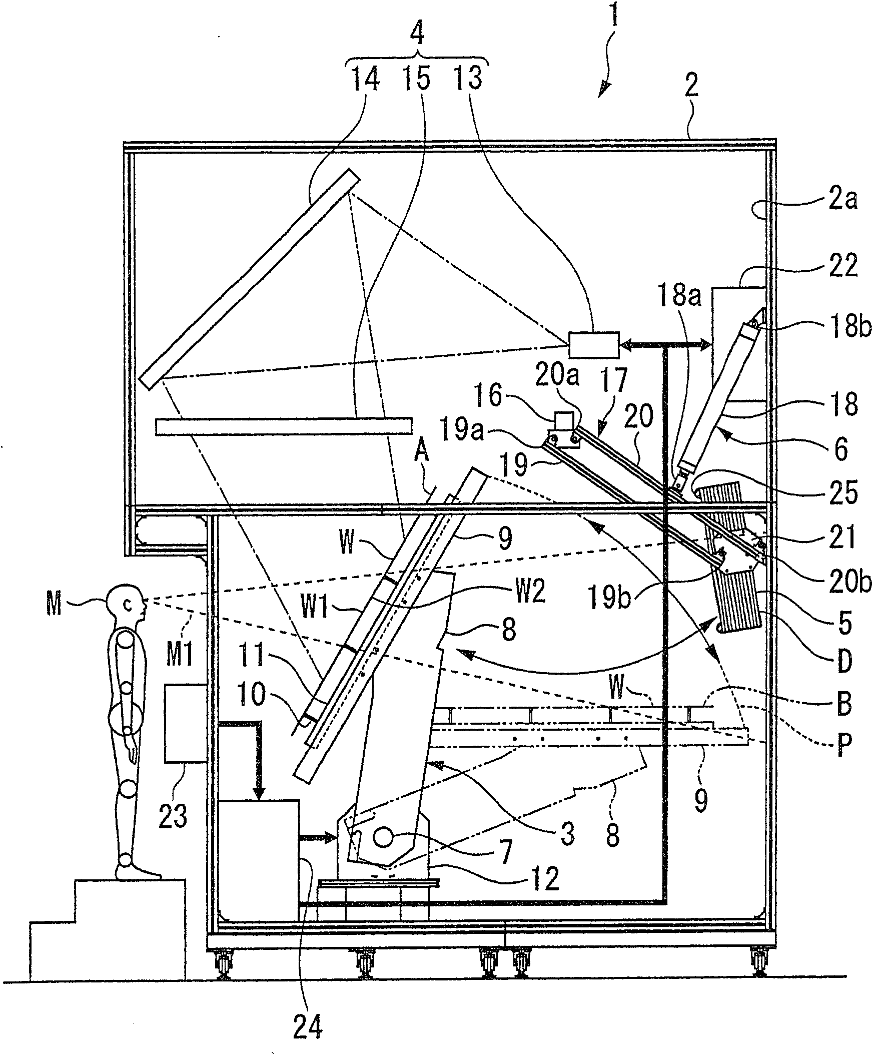
[0040] figure 1 with figure 2 The first embodiment of the present invention is shown. figure 1 The overall view of the substrate inspection device is shown in ; figure 2 Middle represents the enlarged side view.
[0041] Such as figure 1 As shown, the substrate inspection apparatus 1 has: a casing 2, which forms an outer contour; a holder rotating mechanism 3, which rotates a substrate holder 11 holding a substrate W to be inspected; The surface W1 of the pattern is epi-illuminated; the backlight 5 irradiates the back surface W2 opposite to the surface W1 of the substrate W to be inspected; and the moving unit 6 of the backlight 5 . The inner wall surface 2a of the housing 2 is black so that light will not be diffusely reflected. In addition, the stand rotation mechanism 3 has: a turn shaft 7 provided at the turn center; a pair of turn arms 8 rotatably supported on the turn shaft 7 at base end portions of the arms; a pair of stand guides 9 fixed At the front end of eac...
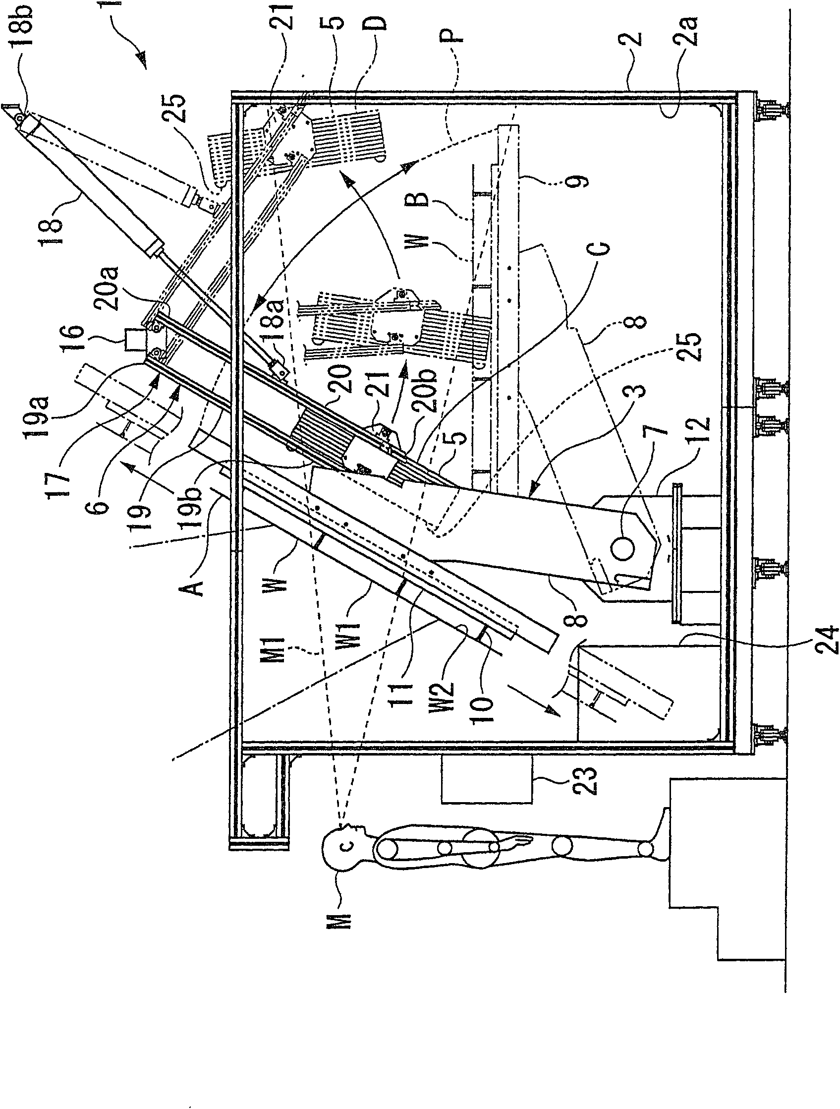
no. 2 Embodiment approach
[0052] image 3 A second embodiment of the present invention is shown, and an enlarged side view of a substrate inspection device is shown. In this embodiment, the same reference numerals are assigned to the same components as those used in the above-mentioned embodiment, and description thereof will be omitted.
[0053] Such as image 3 As shown, in the substrate inspection apparatus 30 of this embodiment, the moving unit 31 for moving the backlight 5 is composed of a rotating arm 32 rotatably supported at the base end on the rotating shaft of the pair of rotating arms 8 . 7 coaxial shaft; actuator 33, which makes the rotating arm 32 rotate. The backlight 5 is fixed to the tip of the swivel arm 32 , and the backlight 5 is rotatable from a retracted position D below the substrate delivery position B of the holder guide 9 to an irradiation position C. As shown in FIG. In addition, one end 33a of the actuator 33 is connected to the rotating arm 32 with a pin, and the other en...
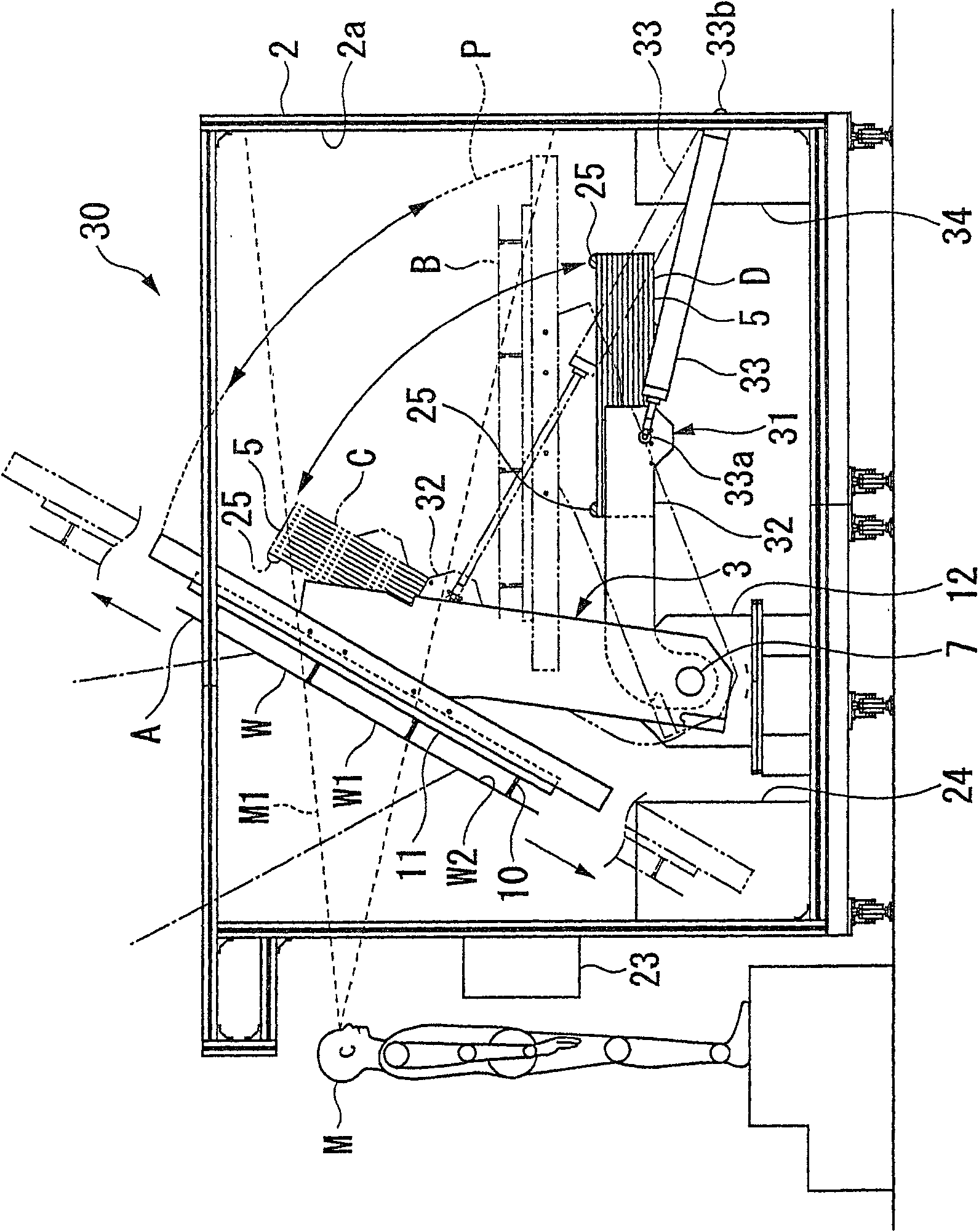
no. 3 Embodiment approach
[0056] Figure 4 A third embodiment of the present invention is shown, and an enlarged side view of a substrate inspection device is shown. In this embodiment, the same reference numerals are assigned to the same components as those used in the above-mentioned embodiment, and description thereof will be omitted.
[0057] Such as Figure 4 As shown, in the substrate inspection apparatus 40 of this embodiment, the moving unit 41 for moving the backlight 5 is constituted by a rotating arm 42 rotatably supported at the base end in the rotating region P of the carriage rotating mechanism 3 . the top; motor 43, which makes the rotating arm 42 rotate. The backlight 5 is fixed to the front end portion of the rotating arm 42 and is set so as to be parallel to the substrate W to be inspected when located at the irradiation position C. As shown in FIG. In addition, the turning arm 42 can move the backlight 5 out of the turning area P of the stand turning mechanism 3 , and move to the ...
PUM
 Abstract
Description
Claims
Application Information
 - R&D Engineer
- R&D Manager
- IP Professional
- Industry Leading Data Capabilities
- Powerful AI technology
- Patent DNA Extraction
Browse by: Latest US Patents, China's latest patents, Technical Efficacy Thesaurus, Application Domain, Technology Topic, Popular Technical Reports.
© 2024 PatSnap. All rights reserved.Legal|Privacy policy|Modern Slavery Act Transparency Statement|Sitemap|About US| Contact US: help@patsnap.com