Rotary type expansion machine
An expander and rotary technology, applied in the field of expanders, can solve problems such as power consumption, and achieve the effects of reliable power recovery, smooth flow rate changes, and improved power recovery efficiency
- Summary
- Abstract
- Description
- Claims
- Application Information
AI Technical Summary
Problems solved by technology
Method used
Image

Examples
Embodiment approach 1
[0062] Embodiment 1 of the present invention will be described. The air conditioner 10 of the present embodiment includes the rotary expander according to the present invention.
[0063]
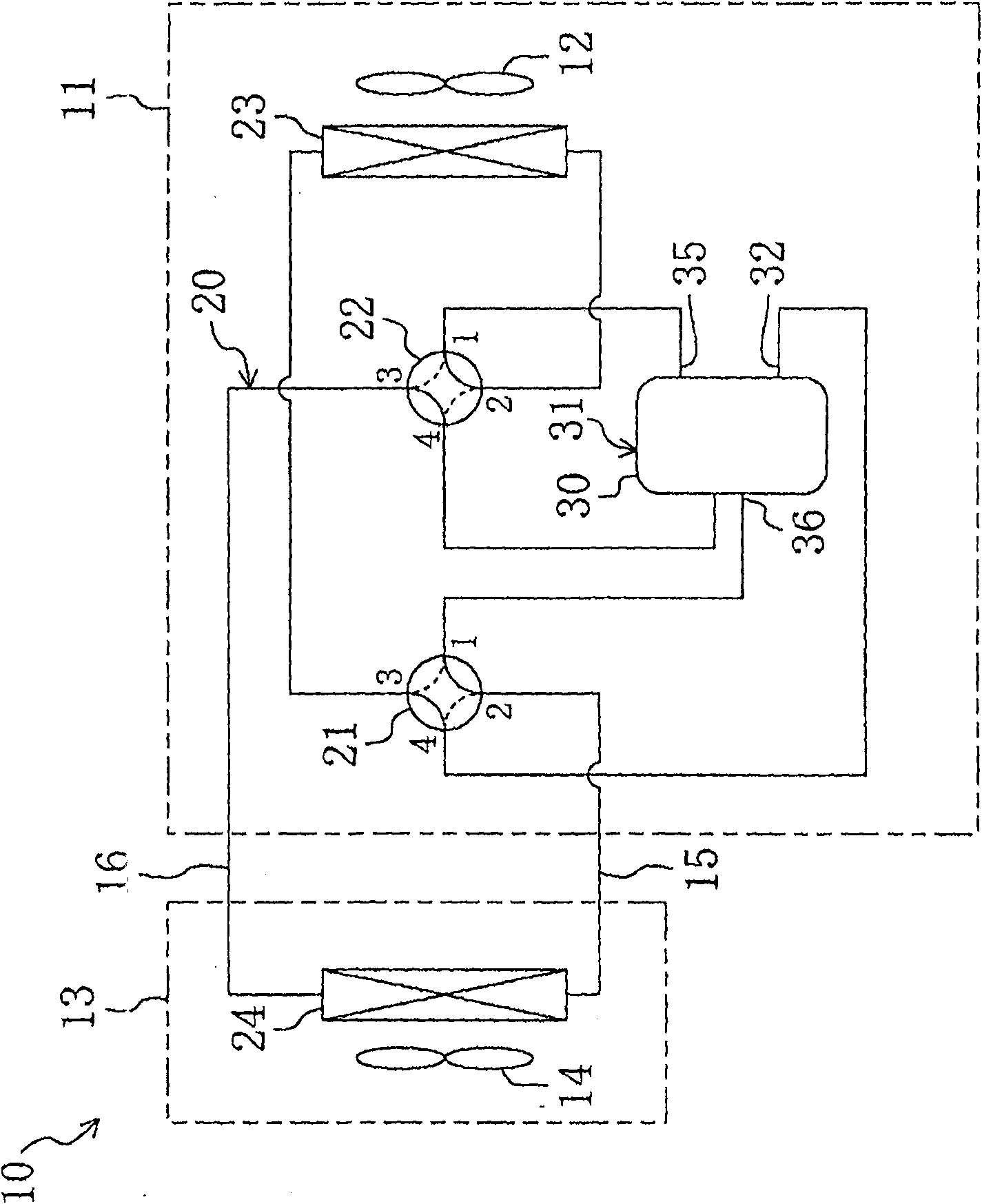
[0064] like figure 1 As shown, the above-mentioned air conditioner 10 is a so-called separate type, and has an outdoor unit 11 and an indoor unit 13 . An outdoor fan 12 , an outdoor heat exchanger 23 , a first four-way switching valve 21 , a second four-way switching valve 22 , and a compression / expansion unit 30 are accommodated in the outdoor unit 11 . An indoor fan 14 and an indoor heat exchanger 24 are housed in the indoor unit 13 . The outdoor unit 11 is installed outdoors, and the indoor unit 13 is installed indoors. In addition, the outdoor unit 11 and the indoor unit 13 are connected by a pair of connecting pipes 15 and 16 . Note that details of the compression / expansion unit 30 will be described later.
[0065] A refrigerant circuit 20 is provided in the air conditioner 10 d...
Embodiment approach 2
[0132] Embodiment 2 of the present invention will be described. Here, in this embodiment, differences from the first embodiment described above will be described.
[0133] like Figure 11 As shown, in the injection passage 37 of the expansion mechanism unit 60 of the present embodiment, a solenoid valve 91 is provided instead of the electric valve 90 of the first embodiment described above. That is, in the present embodiment, the solenoid valve 91 constitutes the flow control means. When the solenoid valve 91 is opened and closed, the high-pressure refrigerant in the injection passage 37 is intermittently circulated. Furthermore, the controller 100 of the present embodiment has a structure in which the electromagnetic valve 91 is opened and closed based on detection values of the high pressure sensor 101 , the low pressure sensor 102 , and the over-expansion pressure sensor 103 .
[0134] In the present embodiment, the solenoid valve 91 is closed under the operating condi...
Embodiment approach 3
[0136] Embodiment 3 of the present invention will be described. Here, regarding this embodiment, differences from the first embodiment described above will be described.
[0137] like Figure 12 As shown, in the injection passage 37 of the expansion mechanism unit 60 of the present embodiment, a differential pressure valve 92 is provided instead of the electric valve 90 of the first embodiment described above. That is, in the present embodiment, the differential pressure valve 92 constitutes the flow control means. The opening degree of the differential pressure valve 92 changes according to the pressure difference between the refrigerant in the expansion chamber 66 and the refrigerant sent from the second rotating mechanism portion 80 to the outflow port 35 .
[0138] like Figure 13 As shown, the above-mentioned differential pressure valve 92 is composed of the following parts: a valve housing 93, which is connected to the injection passage 37; a valve core 95, which is m...
PUM
 Abstract
Description
Claims
Application Information
 - R&D
- Intellectual Property
- Life Sciences
- Materials
- Tech Scout
- Unparalleled Data Quality
- Higher Quality Content
- 60% Fewer Hallucinations
Browse by: Latest US Patents, China's latest patents, Technical Efficacy Thesaurus, Application Domain, Technology Topic, Popular Technical Reports.
© 2025 PatSnap. All rights reserved.Legal|Privacy policy|Modern Slavery Act Transparency Statement|Sitemap|About US| Contact US: help@patsnap.com