High-speed processing screw tap

A kind of screw tapping, high-speed technology, applied in metal processing equipment, manufacturing tools, thread cutting tools, etc., can solve the problems of screw tapping, the shape damage of screw tapping cutting edge, etc., to reduce the load, high speed and smooth high-precision internal thread processing effect

Inactive Publication Date: 2009-12-09
MIMANWA MFG CO LTD +1
View PDF8 Cites 0 Cited by
  • Summary
  • Abstract
  • Description
  • Claims
  • Application Information

AI Technical Summary

Problems solved by technology

[0006] Therefore, the object of the present invention is to provide a screw tap that can solve the problem of damage to the shape of the cutting edge of the screw tap, and can solve the problem of the jump of the screw tap during cutting, and can smoothly process internal threads with high speed and high precision.

Method used


Image

  • High-speed processing screw tap
  • High-speed processing screw tap
  • High-speed processing screw tap

Examples


Embodiment Construction

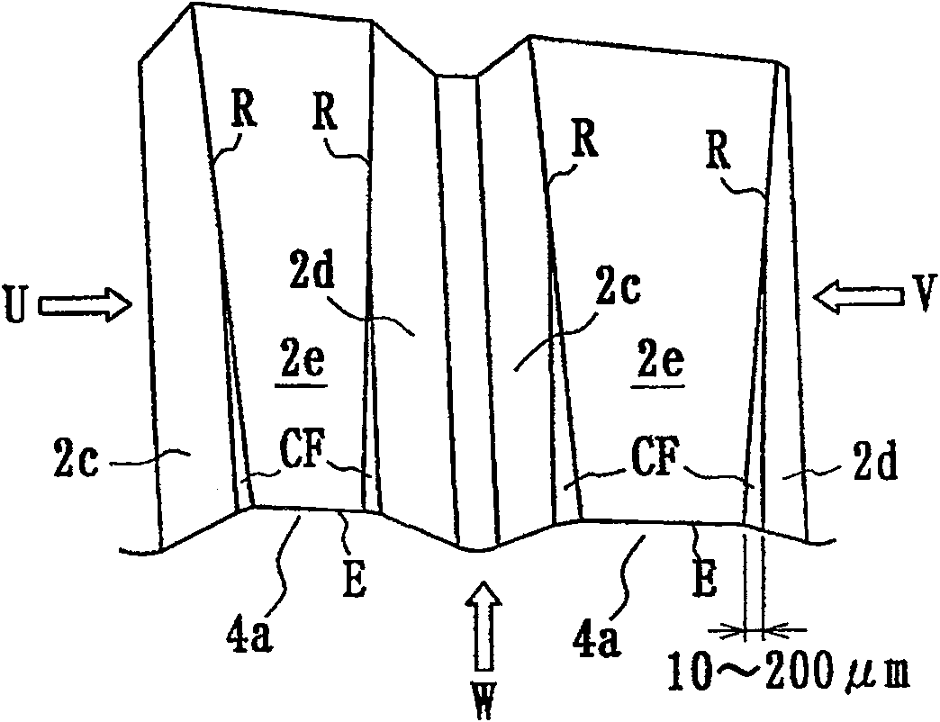
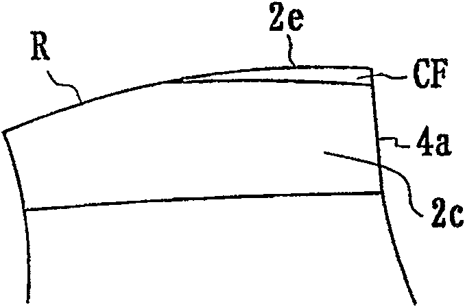
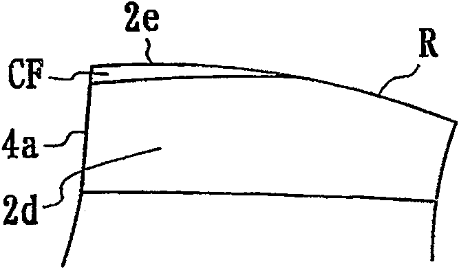
[0031] Embodiments of the present invention will be described in detail below with reference to the drawings through examples. here, Figure 1a , Figure 1b , Figure 1c , Figure 1d In Fig. 2, it shows a side view after enlarging part A in an embodiment of the screw tap for high-speed machining of the present invention and showing along the groove, and a side view viewed from the directions of arrows U, V, and W in the figure, and Figure 2a , Figure 2b The side view and the front view of the present invention are represented in the figure; Figure 3a , Figure 3b , Figure 3c In the explanatory diagram showing the formation procedure of the chamfered portion along the tapped ridge line in the above-mentioned embodiment, the same symbols are used for the same parts as those in the previous example.

[0032] That is, in the screw tap 1 for high-speed machining in this embodiment, as shown in FIG. The cutting edge of part 2 is used to cut and process the internal threa...


PUM


Abstract

The present invention is a screw tap for high-speed machining, which is rotated by a working machine and pushed to move at the same time, and uses the cutting edge (E) of the threaded part (2) to cut and process the internal thread, in the threaded part (2) The guide taper (2a) of the thread mountain starts from the cutting edge (E), along the relief surface (2c) of the thread mountain and the ridgeline (R) between the cutting surface (2d) and the mountain top surface (2e), and there are Chamfer (CF). Therefore, the shape of the cutting edge of the tap leading cone can be stably maintained, so that high-speed and high-precision internal thread processing can be smoothly performed, and the tap can have a long service life.

Description

technical field [0001] The present invention relates to a tap for high-speed machining that cuts internal threads by using a cutting edge of a threaded portion. Background technique [0002] The thread has the "fastening function" of fastening the object, and the "push function" of pushing the object forward, and any function is as follows Figure 5a As shown, the maximum effect can be exerted when the two sides of the male thread M and the female thread F are in surface contact. However, in reality, there are tolerances between the external thread and internal thread, and there are tolerances in the tool or machine tool that processes it, so the possibility of surface contact is very low, even with tightly fitted threads , strictly speaking, just yields Figure 5b The state shown: the contact between the external thread M and the two sides of the internal thread F is only a point contact in the part indicated by the symbol P in the figure. When fastening, due to the strong...

Claims


Application Information

Patent Timeline
Patent Type & Authority Patents(China)
IPC IPC(8): B23G5/06
CPCY10T408/90467B23G5/06Y10T408/906
Inventor 赤木贞之三井雅夫威廉德·E·韩德尔
Owner MIMANWA MFG CO LTD
Why Eureka
Try Eureka