
Method for welding parts

A technology for parts and welding parameters, applied in the field of ultrasonic welding, which can solve problems such as temperature fluctuations and fluctuations in the quality of welding results

Active Publication Date: 2009-12-02
SCHUNK ULTRASCHALLTECHN
View PDF18 Cites 2 Cited by
  • Summary
  • Abstract
  • Description
  • Claims
  • Application Information

AI Technical Summary

Problems solved by technology

[0009] If different materials are used regardless of the same overall cross-section, if the wires are positioned differently in the tool, i.e. between the sonotrode and anvil, or if temperature fluctuations or environmental influences occur, the quality of the welding result may fluctuate if necessary

Method used


Image

  • Method for welding parts
  • Method for welding parts
  • Method for welding parts

Examples


Embodiment Construction

[0035] The invention is explained below with the aid of a rope to be welded, but should not be restricted thereby. On the contrary, the invention also extends to the welding of plastic parts.

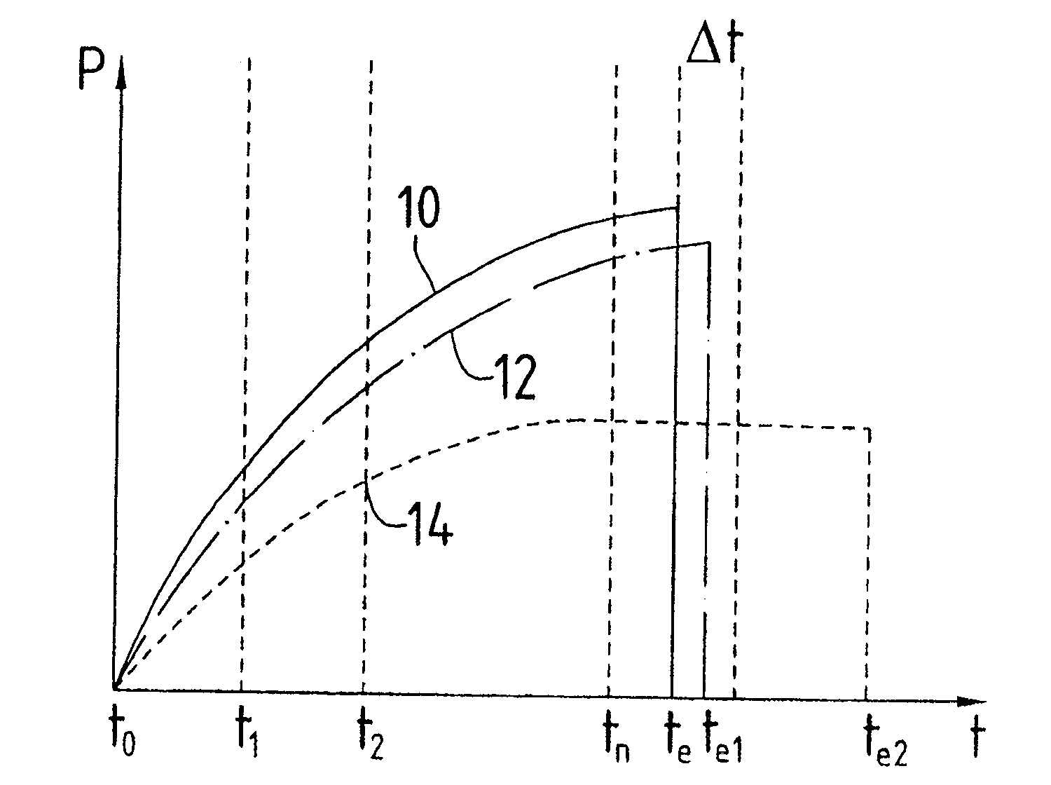
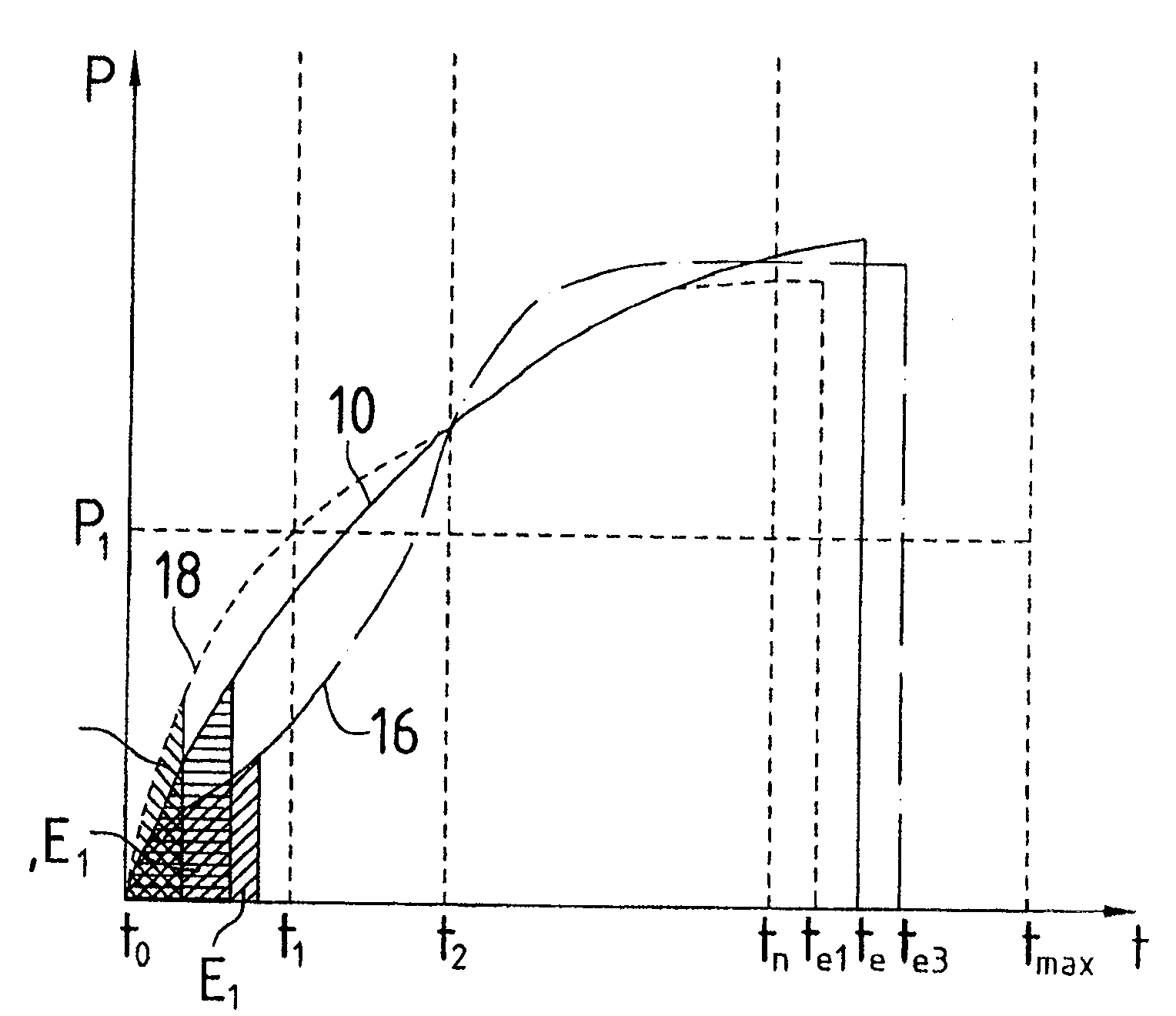
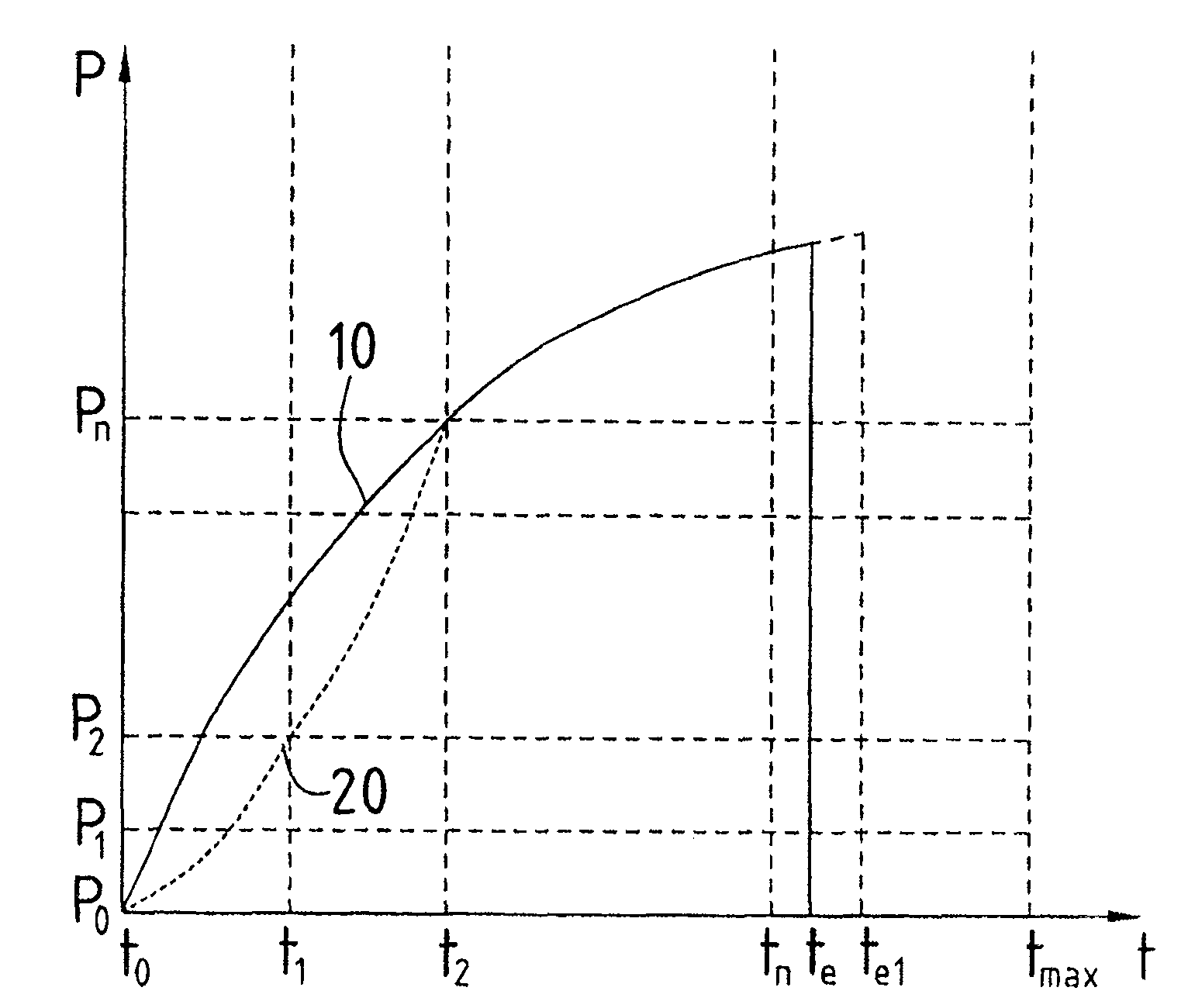
[0036] In order to weld a cable by means of ultrasound according to the prior art, values ​​stored in a memory relating to, for example, pressure, amplitude, tool size and energy input are called based on its overall cross section. Welding of the rope is then carried out in which a power-time curve is established from figure 1 It can be seen and is marked with the reference number 10 . Therefore, the area under the correspondingly drawn curve 10 corresponds to the energy input represented by:

[0037] E = ∫ t = 0 t = te Pdt

[0038] where P = power and t = time.

[0039] In this embodiment, the curve 10 co...


PUM


Abstract

The invention relates to a device for ultrasonic welding comprising at least one generator, a converter and a sonotrode, based on a theoretical curve (10 ), a method for ultrasonic welding of parts, especially rope welding, in which the welding process consistent with the theoretical curve starts at time t 0 and the end time t e in between. In order to obtain good welding results reproducibly, it is recommended to measure the actual curves (16, 18) of the time-dependent parameters during welding, where at t 0 and t e In the intervening time intervals, the actual curve is compared with the target curve, and at least one welding-influencing process parameter is changed in accordance with existing deviations, so that an adaptation of the target curve to the actual curve takes place during the subsequent welding.

Description

technical field [0001] The invention relates to a method for ultrasonic welding, in particular rope welding, of parts, by means of an ultrasonic welding device comprising at least one generator, a converter and a sonotrode, on the basis of a welded connection which satisfies the stated requirements The above is carried out according to the theoretical curve of the time-dependent welding parameters, wherein the welding process consistent with the theoretical curve starts at the starting time t 0 and the end time t e between the actual curves of time-dependent parameters measured during the welding process of the parts, at t 0 and t e The actual curve is compared with the theoretical curve in the time interval between. Background technique [0002] In order to be able to weld joints of different types of material well and without prior tests, according to DE-A-198 10 509, the ultrasound input into the welded part is measured as the measurement signal in interaction with a j...

Claims


Application Information

Patent Timeline
Patent Type & Authority Patents(China)
IPC IPC(8): B23K20/10B29C65/08B06B1/02B29C65/00
CPCB29C66/92921B29C66/92443B23K2201/32B29C66/9516B29C66/9241B29C65/08B29C66/9592B29C66/9512B23K20/10B29C66/9513B23K2101/32B06B1/02B29C65/18
Inventor K·戈登
Owner SCHUNK ULTRASCHALLTECHN
Learn More