Large rod-cable extending arm extension driving mechanism
A technology of driving mechanism and extending arm, which is applied in the direction of motor vehicles, space navigation equipment, space navigation aircraft, etc., can solve the difficulty in realizing the rotary support of the spiral sleeve, the low machining accuracy of the four-thread spiral sleeve, the manufacturing accuracy, and the manufacturing process. Require high-level problems, achieve the effect of light weight, simple structure, and low processing and manufacturing technology requirements
- Summary
- Abstract
- Description
- Claims
- Application Information
AI Technical Summary
Problems solved by technology
Method used
Image

Examples
specific Embodiment approach 1
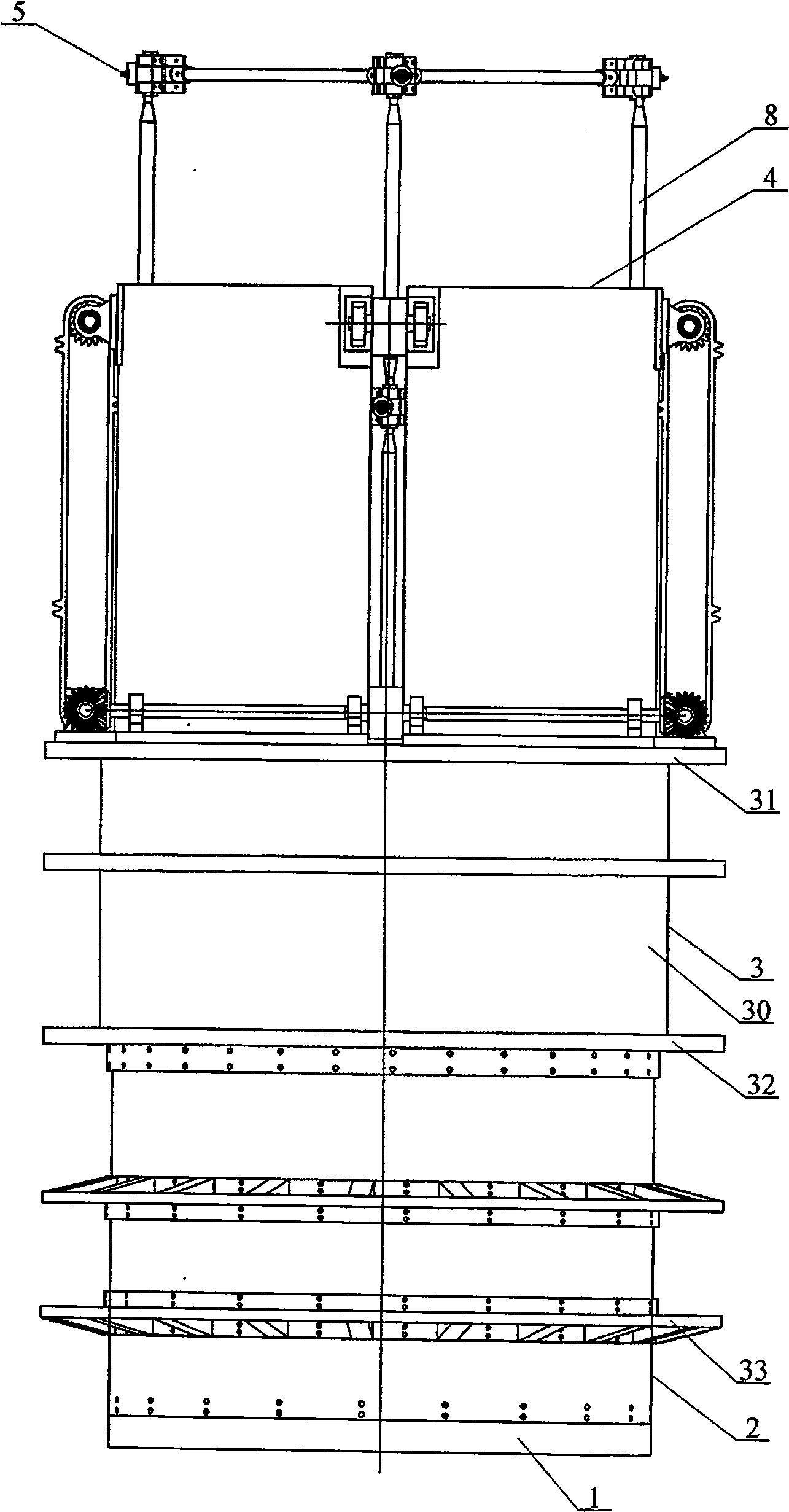
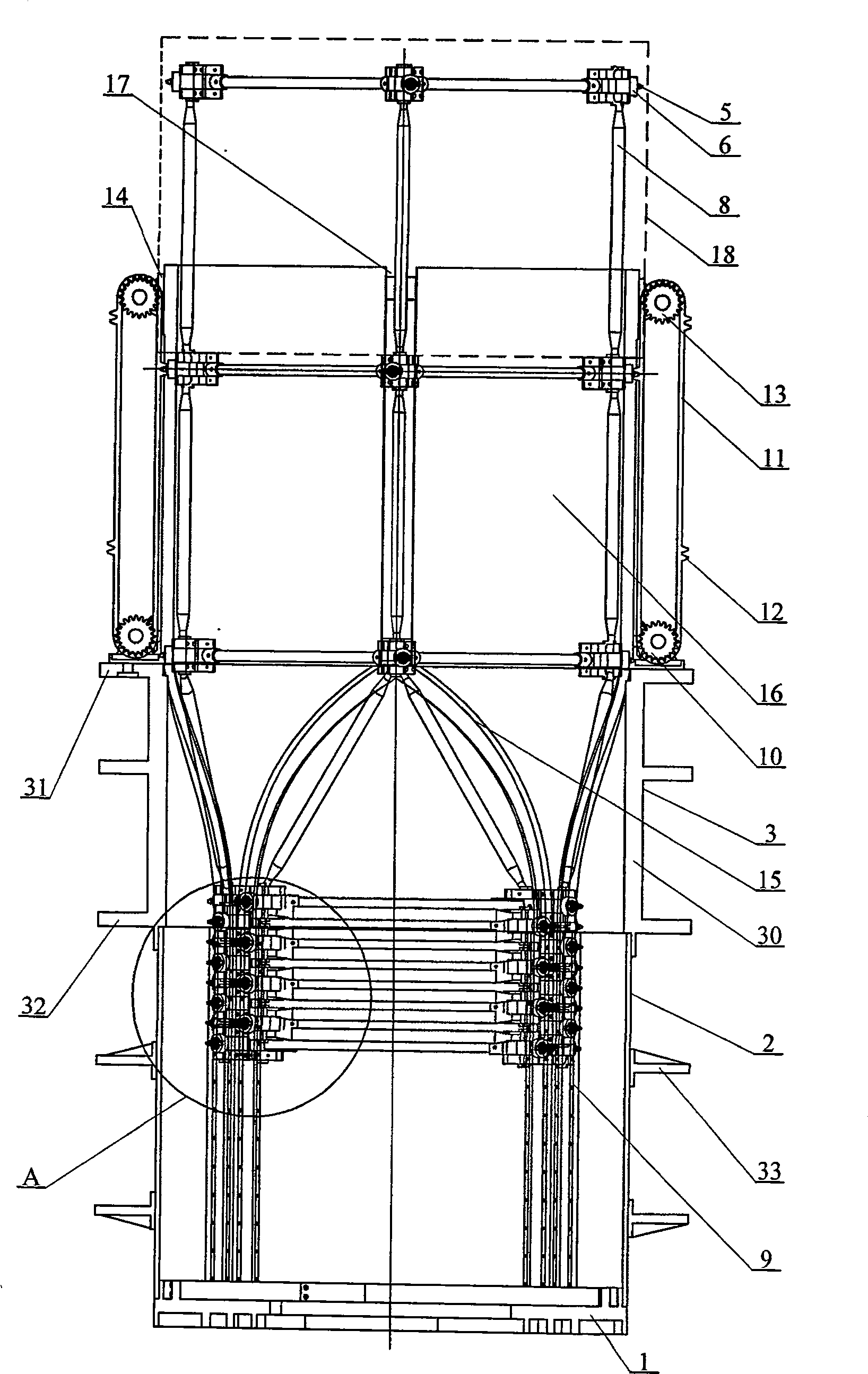
[0007] Specific implementation mode one: combine Figure 1 to Figure 8 This embodiment is described. This embodiment consists of a bottom end cover 1, a retracting sleeve 2, a derotation sleeve 3, four sets of chain lifting mechanisms, a driving sleeve 4, an extension arm tooth piece 5, a roller 6, and a cable rod type extension arm assembly, eight linear tracks 9 and a reversing transmission mechanism; each group of chain lifting mechanisms is composed of a driving sprocket 10, a chain 11, a chain tooth 12, a driven sprocket 13, and a sprocket support 14; The bottom end cover 1, the retracting sleeve 2, the derotation sleeve 3, and the driving sleeve 4 are fixedly connected together from bottom to top in order to provide a container for the cable rod type extension arm in the folded state. The cloth is provided with four groups of curved grooves, each group of curved grooves is composed of two symmetrically arranged curved grooves 15, and the inner wall of the retracting slee...
specific Embodiment approach 2
[0008] Specific implementation mode two: combination Figure 5 To illustrate this embodiment, the reversing transmission mechanism of this embodiment is composed of a motor 19, a first short transmission shaft 20, a second short transmission shaft 21, a first long transmission shaft 22, a second long transmission shaft 23, and a bevel gear pair 24 ; The first short transmission shaft 20, the second short transmission shaft 21, the first long transmission shaft 22 and the second long transmission shaft 23 are respectively fixed with the driving sprocket 10, and the motor 19 and the first short transmission shaft 20 drive connection, between the first short transmission shaft 20 and the first long transmission shaft 22, between the first long transmission shaft 22 and the second long transmission shaft 23 and between the second long transmission shaft 23 and the second short transmission shaft 21 respectively The driving ring is formed through the transmission connection of the ...
specific Embodiment approach 3
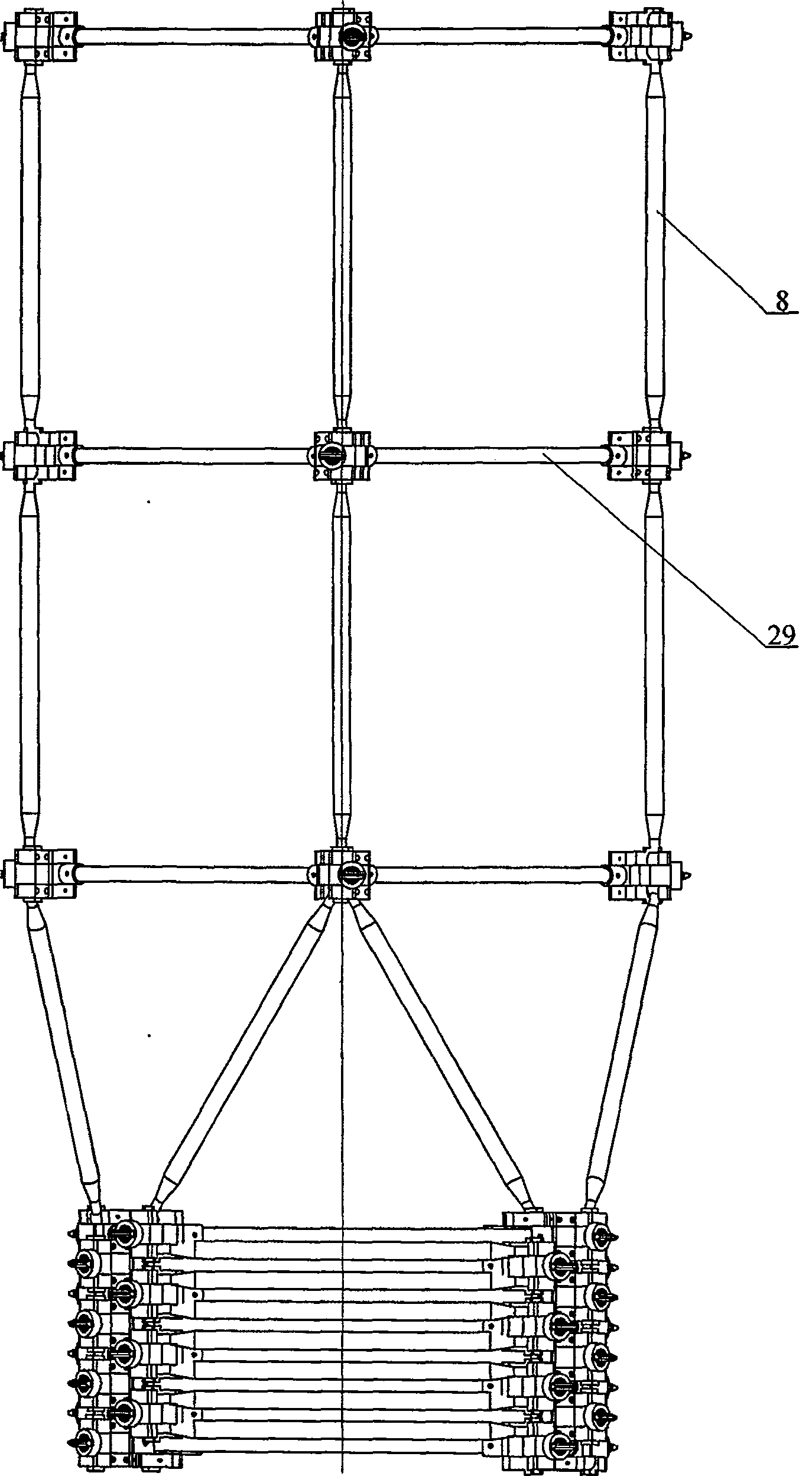
[0009] Specific implementation mode three: combination figure 2 , Figure 6 Illustrate this embodiment, the cable rod type extension arm 18 of this embodiment is made up of lower corner block 25, four middle corner blocks 26, upper corner block 27, ball hinge 28, four cross bars 29, four connecting rods 8; A cross bar 29 is rigidly connected with four middle corner blocks 26 to form a square rigid plane, and the middle corner block 26 is fixedly connected with the upper corner block 27 and the lower corner block 25 to form two ball sockets. The four connecting rods 8 are vertically arranged on Between two adjacent square rigid planes and located at the four corners of the square rigid planes, both ends of each connecting rod 8 are respectively hinged with the ball sockets corresponding to the two adjacent square rigid planes. Such arrangement has the advantages of simple structure and reliable operation. Other components and connections are the same as those in the first em...
PUM
 Abstract
Description
Claims
Application Information
 - Generate Ideas
- Intellectual Property
- Life Sciences
- Materials
- Tech Scout
- Unparalleled Data Quality
- Higher Quality Content
- 60% Fewer Hallucinations
Browse by: Latest US Patents, China's latest patents, Technical Efficacy Thesaurus, Application Domain, Technology Topic, Popular Technical Reports.
© 2025 PatSnap. All rights reserved.Legal|Privacy policy|Modern Slavery Act Transparency Statement|Sitemap|About US| Contact US: help@patsnap.com