High efficient laminated graphic discharge gap device
A discharge gap and stacked technology, which is applied in the direction of circuits, spark gaps, electrical components, etc., can solve the problem of unexplained sparkover suppression, the uncertainty of the constant value or value range of the voltage equalizing capacitor, and the undetermined discharge electrode material And other problems, to achieve the effect of controlling the ignition breakdown voltage, no arc leakage, and protecting safety
- Summary
- Abstract
- Description
- Claims
- Application Information
AI Technical Summary
Problems solved by technology
Method used
Image
Examples
Embodiment 1
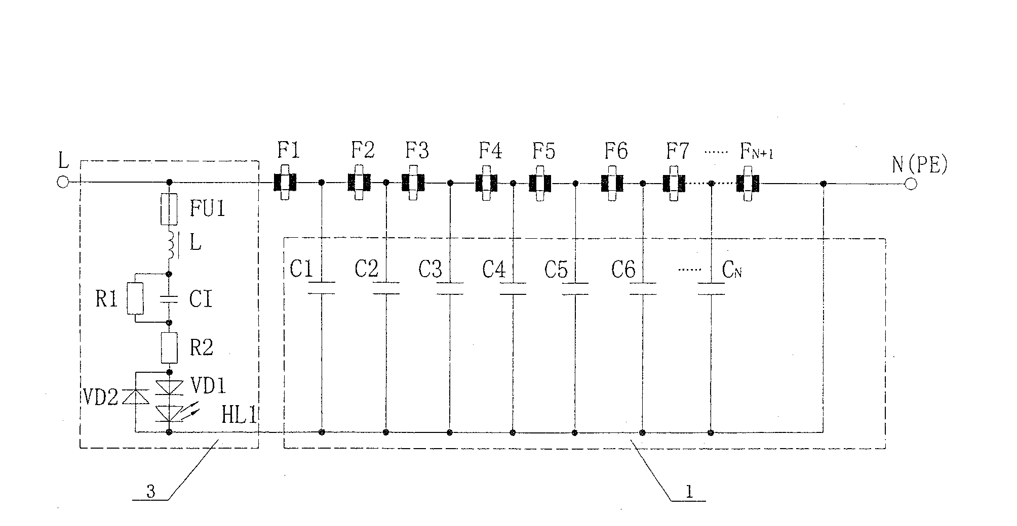
[0056] The circuit structure of the high-efficiency graphite laminated discharge gap device in this embodiment is as follows Figure 4 As shown, it includes eight graphite discharge gaps, a π-shaped connection capacitor group 1 composed of seven capacitors with the same capacitance value, a current fuse 2 and an indicating circuit 3 . Each graphite discharge gap is connected in series, wherein, the first graphite discharge gap F 1 Connect with live wire, the last discharge gap F 8 Grounded, π-shaped connection to each capacitor C in the capacitor bank 1 、C 2 、C 3 、C 4 、C 5 、C 6 、C 7 One end is connected to the conductive part between the two graphite discharge gaps, and the other end is grounded; the end of the π-shaped connection capacitor group circuit is connected to the current fuse 2; one end of the indicating circuit is connected to the first graphite discharge gap F 1 On the connecting piece with the live wire L, the other end is grounded. The structure of indi...
Embodiment 2
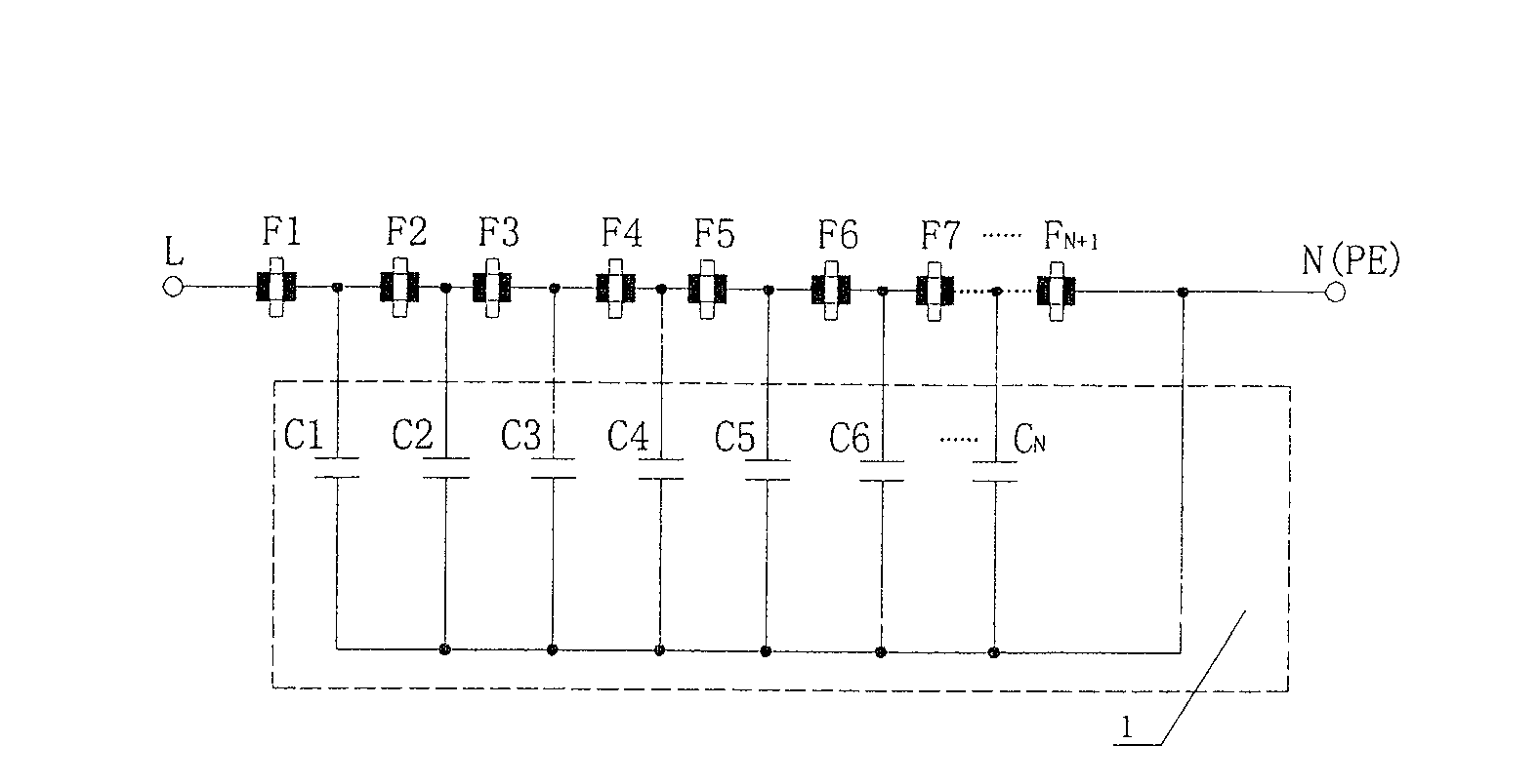
[0060] The circuit structure of the high-efficiency graphite laminated discharge gap device in this embodiment is as follows figure 1 As shown, it includes nine graphite discharge gaps and a π-shaped connection capacitor group 1 composed of eight capacitors with the same capacitance value, and each graphite discharge gap is connected in series, wherein the first graphite discharge gap F 1 Connect with live wire, the last discharge gap F 9 Grounding, one end of each capacitor in the π-shaped connection capacitor group is connected to the conductive member between the two graphite discharge gaps, and the other end is grounded.
[0061] In the above circuit, the value of each capacitor of the π-shaped connection capacitor group is determined according to C=In / 2πfVK, where In=I / N=3.2 / 8A, f≈18×10 3 Hz, V=3000V, K=3, into the above formula calculation, C≈390pF.
[0062] The electronic components in the above circuit are assembled in Figure 5 In the box body 13 shown, the size of...
Embodiment 3
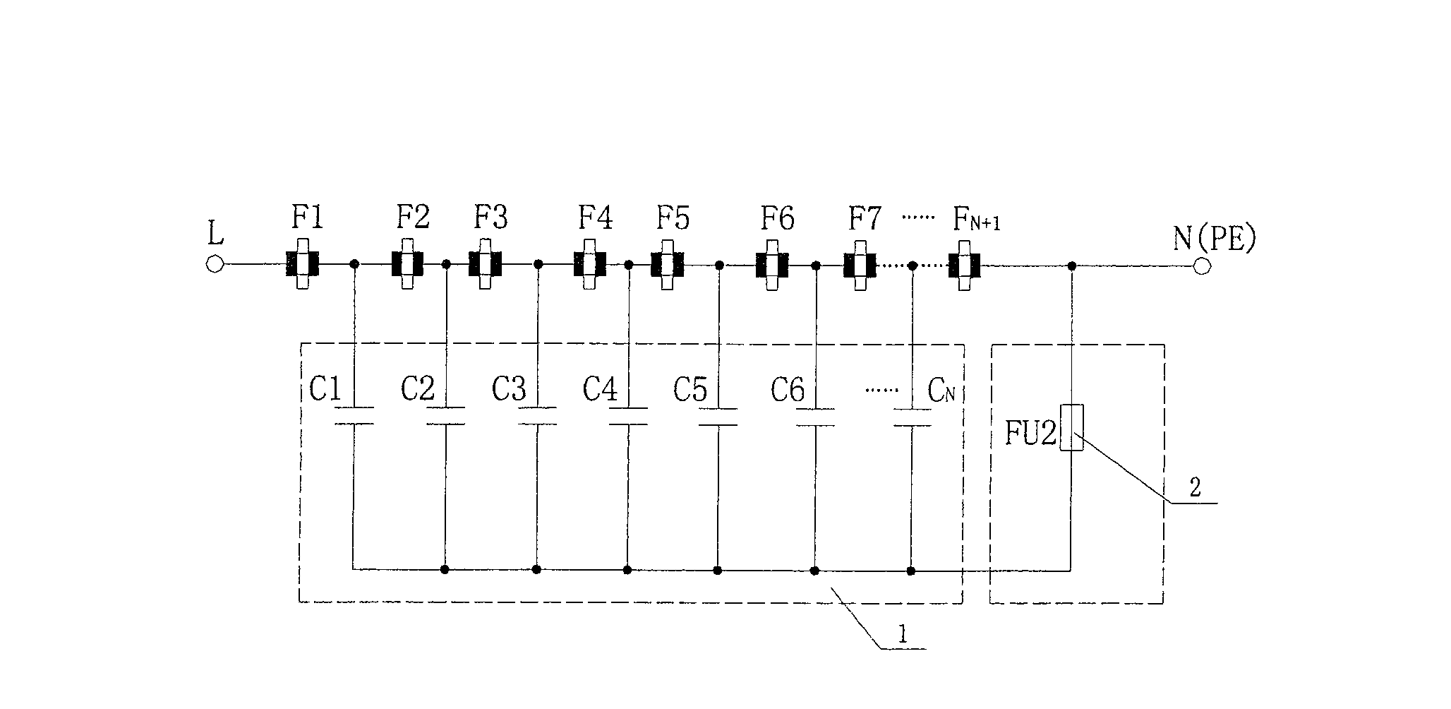
[0065] The circuit structure of the high-efficiency graphite laminated discharge gap device in this embodiment is as follows figure 2 As shown, it includes ten graphite discharge gaps, a π-connected capacitor group 1 composed of nine capacitors with the same capacitance value, and a current fuse 2 . Each graphite discharge gap is connected in series, wherein, the first graphite discharge gap F 1 Connect with live wire, the last discharge gap F 10 Grounding, one end of each capacitor in the π-shaped connection capacitor group is connected to the conductive member between the two graphite discharge gaps, the other end is grounded, and the end of the π-shaped connection capacitor group circuit is connected to the current fuse 2 .
[0066] In the above circuit, the value of each capacitor of the π-shaped connection capacitor group is determined according to C=In / 2πfVK, where In=I / N=4.5 / 9 A, f≈18×10 3 Hz, V=3000V, K=2, into the above formula calculation, C≈737pF.
[0067] The e...
PUM
 Abstract
Description
Claims
Application Information
 - R&D
- Intellectual Property
- Life Sciences
- Materials
- Tech Scout
- Unparalleled Data Quality
- Higher Quality Content
- 60% Fewer Hallucinations
Browse by: Latest US Patents, China's latest patents, Technical Efficacy Thesaurus, Application Domain, Technology Topic, Popular Technical Reports.
© 2025 PatSnap. All rights reserved.Legal|Privacy policy|Modern Slavery Act Transparency Statement|Sitemap|About US| Contact US: help@patsnap.com


