
Besonance sensor for measuring liquid density

A liquid density and sensor technology, applied in the direction of measuring devices, specific gravity measurement, instruments, etc., can solve the problems of difficult stability and reliability of work, affecting the accuracy of measurement, etc., and achieve the effect of simple mode shape, small heat-affected zone, and stable and reliable work

Inactive Publication Date: 2009-08-12
BEIHANG UNIV
View PDF3 Cites 0 Cited by
  • Summary
  • Abstract
  • Description
  • Claims
  • Application Information

AI Technical Summary

Problems solved by technology

Chinese patent 89217849.3 discloses a vibrating diaphragm density sensor. Its diaphragm is fixed on the base through a die, and there is a slope attenuation band between the fixed periphery and the effective vibration surface, and it is separated. The vibrator of the type density sensor uses an electromagnetic coil, and the vibrator uses a semiconductor strain gauge, and it must be installed on both sides of the diaphragm. If the density of the liquid is to be measured, both sides of the diaphragm must be in contact with the liquid. , in fact, this structure needs to be completely insulated for protection, otherwise it will affect the accuracy of the measurement, and the work is not easy to be stable and reliable

Method used


Image

  • Besonance sensor for measuring liquid density
  • Besonance sensor for measuring liquid density
  • Besonance sensor for measuring liquid density

Examples


Embodiment Construction

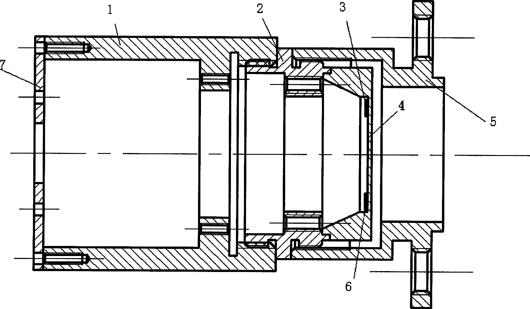
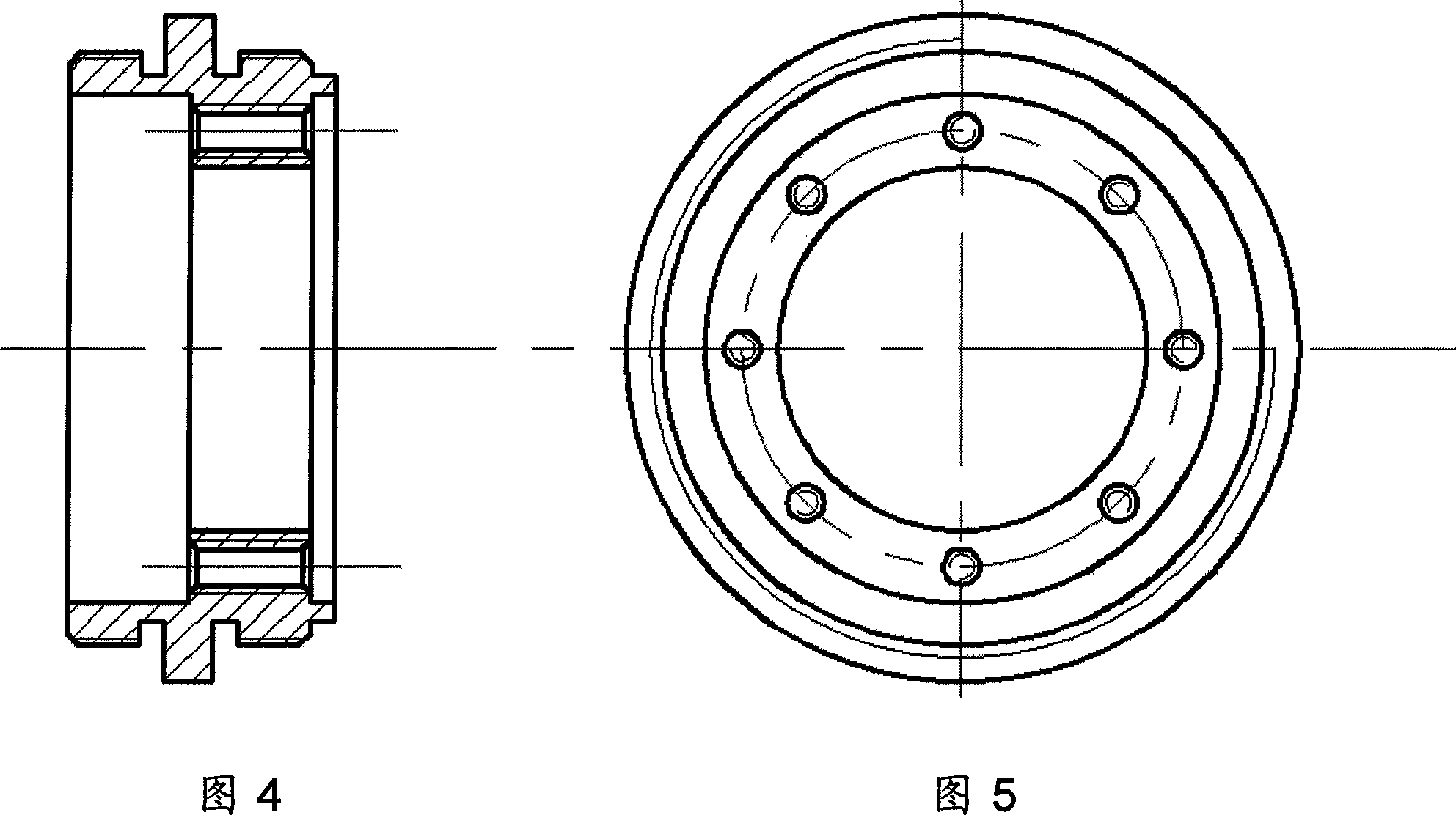
[0020] Such as figure 1 As shown in —10, the present invention consists of a diaphragm circuit box 1, a diaphragm base 2, a piezoelectric vibration exciter 3, a diaphragm 4, a diaphragm box flange structure 5, a piezoelectric vibration pickup 6 and an end cover 7. The diaphragm 4 and the diaphragm base 2 are welded together by vacuum electron beam welding, the diaphragm base 2 and the diaphragm box flange structure 5 are connected by threads, and the diaphragm base 3 and the diaphragm circuit box 1 pass through Threaded connection, the piezoelectric vibrator 3 and the piezoelectric vibrator 6 are pasted on the same side of the diaphragm, which is different from the conventional diaphragm density sensor. The liquid to be tested is connected to the liquid container through the box flange connection 5, and the end cover 7 covers the diaphragm circuit box 1.

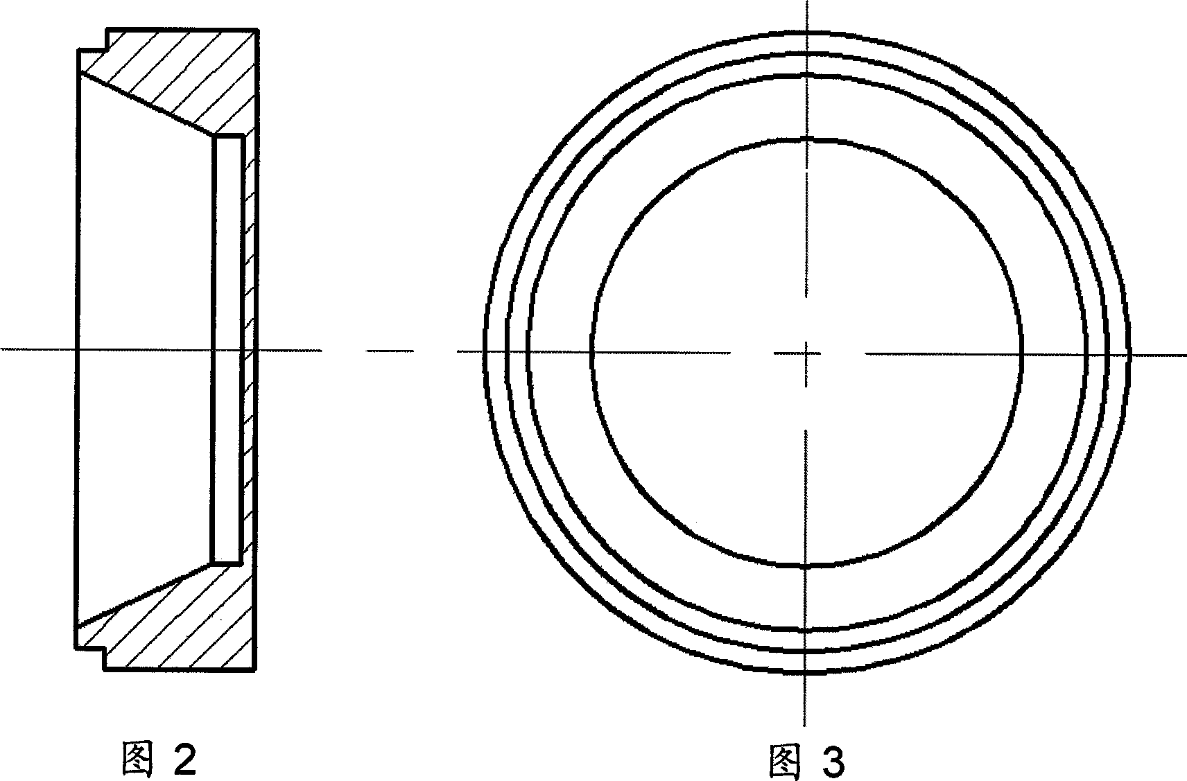
[0021] As shown in Figures 2 and 3, the diaphragm 4 is the most important part of the sensor. Therefore, elastic alloy steel ...


PUM

PropertyMeasurementUnit
thicknessaaaaaaaaaa

Abstract

A resonant sensor for measuring liquid density, which includes a diaphragm, a diaphragm base, a piezoelectric exciter, a piezoelectric pickup, a diaphragm circuit box, a flange structure of a diaphragm case, and an end cover. In the structure of the diaphragm, the diaphragm processing must ensure the flatness and parallelism of the two planes of the diaphragm. The diaphragm and the diaphragm base are welded into a whole by vacuum electron beam welding. The flange structure of the diaphragm box and the diaphragm The base is connected by threads, the piezoelectric vibrator and the piezoelectric vibrator are glued on the same side of the diaphragm respectively, and the diaphragm circuit box and the diaphragm base are connected by threads. The system has the advantages of high measurement accuracy, stability and reliability, simple structure and small volume.

Description

Technical field [0001] The invention relates to a resonance type measuring liquid density sensor, which is used for measuring liquid density. Background technique [0002] At present, many researchers have been studying the method of measuring density using the resonance principle, but most of them are in the research and development stage and have not yet reached the stage of finalization. Since the measurement of density is often affected by temperature and pressure, in addition to measuring the mass and volume, the pressure and temperature must also be accurately measured. Chinese Patent No. 89217849.3 discloses a vibrating diaphragm density sensor. Its diaphragm is fixed on the base by a die, and there is an inclined attenuation band between the fixed periphery and the effective vibrating surface, and the diaphragm is separated. The vibration exciter of the type density sensor uses electromagnetic coils, and the vibration pickup uses semiconductor strain gauges, and they must...

Claims


Application Information

Patent Timeline
Patent Type & Authority Patents(China)
IPC IPC(8): G01N9/24
Inventor 樊尚春张欲晓
Owner BEIHANG UNIV
Learn More