Combined fan
A combination and fan technology, which is applied to non-variable pumps, components of pumping devices for elastic fluids, pump devices, etc., can solve problems such as flow field interference, noise value increase, and noise excitation
- Summary
- Abstract
- Description
- Claims
- Application Information
AI Technical Summary
Problems solved by technology
Method used
Image
Examples
no. 1 example
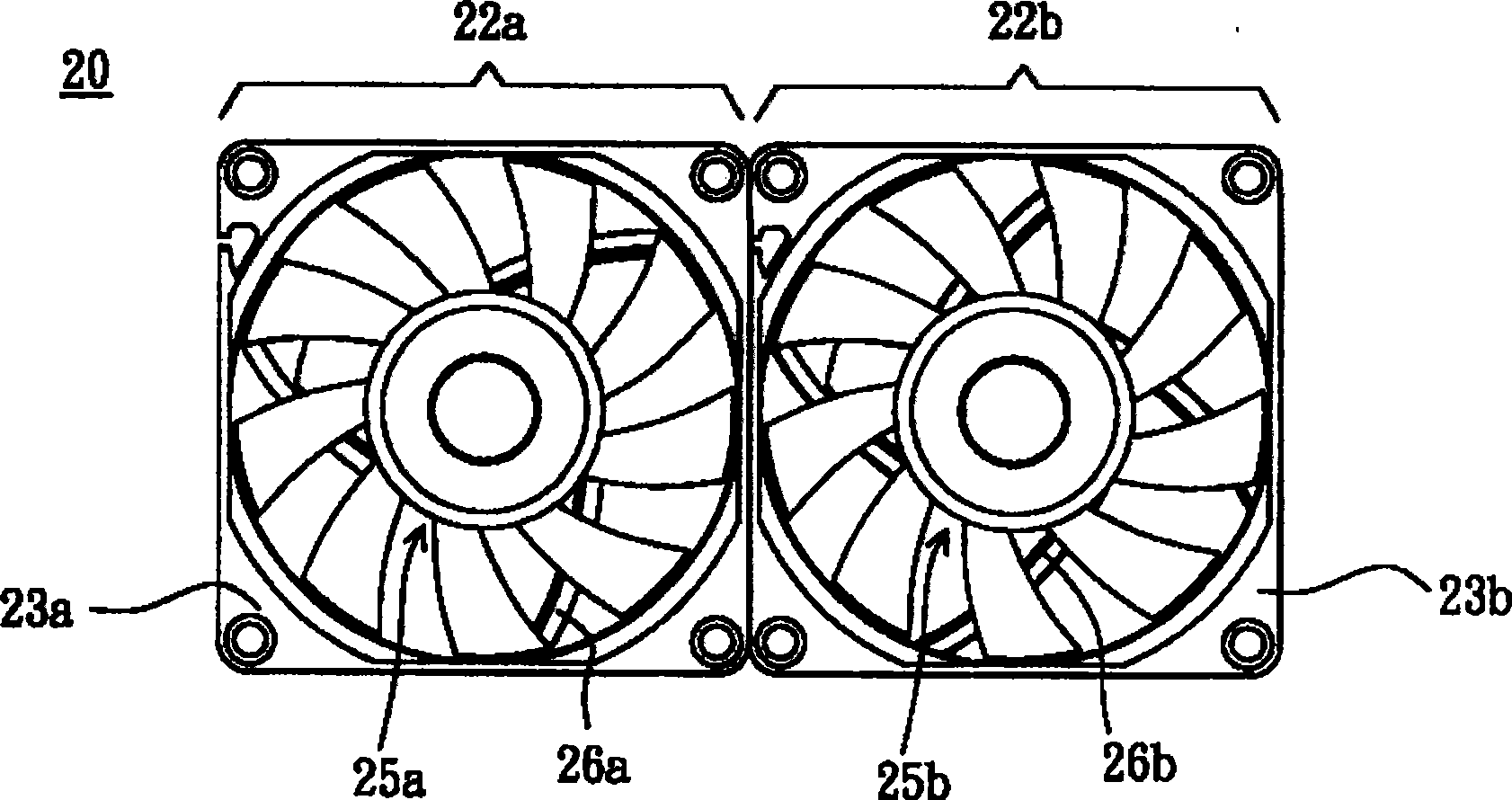
[0024] Please also refer to Figure 2A and Figure 2B , Figure 2A shows a top view of a combined fan according to a first embodiment of the present invention, and Figure 2B show Figure 2B Bottom view of the combined fan. Here, it should be noted that, for the convenience of explanation, this embodiment only takes two fans as an example, but this embodiment is not limited to this, users can connect more than three fans in parallel according to their needs. Can. In this embodiment, the combined fan 20 includes at least two fans 22a, 22b. The fan 22a is, for example, an axial fan, including a frame 23a, a motor base 24a, an impeller 25a, and at least one flow guide assembly 26a.
[0025] The frame 23a has an opening, and the openings form an air inlet and an air outlet at two ends of the frame. The motor base 24a is disposed in the opening, and can be disposed at the air inlet or the air outlet according to the needs of the user. In this embodiment, the motor base 24a is...
no. 2 example
[0030] Please also refer to Figure 3A and Figure 3B , Figure 3A shows a top view of a combined fan according to a second embodiment of the present invention, and Figure 3B show Figure 3B Bottom view of the combined fan. The combined fan 30 includes at least two fans 32 a, 32 b and a fan tray 34 . Here, it should be noted that, for the convenience of explanation, this embodiment only takes two fans as an example, but this embodiment is not limited to this, users can connect more than three fans in parallel according to their needs. Can.
[0031] The main features of the two fans 32a, 32b in this embodiment are similar to the fans 22a, 22b in the first embodiment. The fan 32a and the fan 32b are two very similar fans. The frame, the motor base, and the impeller used in it, and the number of blades on the impeller are the same, and the main difference between the two is that the number of the flow guide assembly 36a is different from the number of the flow guide assemb...
no. 3 example
[0036] Please also refer to Figure 4A and Figure 4B , Figure 4A shows a top view of a combined fan according to a third embodiment of the present invention, and Figure 4B show Figure 4A Bottom view of the combined fan. Here, it should be noted that, for the convenience of description, this embodiment only takes two fans 42a, 42b as an example, but this embodiment is not limited to this, and users can connect more than three fans in parallel at the same time depending on their needs. A fan is also available.
[0037] In this embodiment, the combined fan 40 includes a frame body 43, motor bases 44a, 44b, and impellers 45a, 45b to form two fans 42a, 42b. The frame body 43 is integrally formed and has a plurality of openings for forming an air outlet and an air inlet respectively in the frame body 43 . The motor bases 44a, 44b are respectively arranged in the openings, and can be installed at the air inlet or the air outlet according to the needs of the user. In this em...
PUM
 Abstract
Description
Claims
Application Information
 - Generate Ideas
- Intellectual Property
- Life Sciences
- Materials
- Tech Scout
- Unparalleled Data Quality
- Higher Quality Content
- 60% Fewer Hallucinations
Browse by: Latest US Patents, China's latest patents, Technical Efficacy Thesaurus, Application Domain, Technology Topic, Popular Technical Reports.
© 2025 PatSnap. All rights reserved.Legal|Privacy policy|Modern Slavery Act Transparency Statement|Sitemap|About US| Contact US: help@patsnap.com


