Eureka AIR delivers breakthrough ideas for toughest innovation challenges, trusted by R&D personnel around the world.

Address-control-based optical channel selection device

A technology of address control and optical splitting device, which is applied in the direction of data exchange through path configuration, electromagnetic wave transmission system, digital transmission system, etc. It can solve the problems that cannot meet the number of IP addresses, limit the application of optical switching, and migrate each port. Achieve low requirements, avoid loss and error, and increase the speed of route selection

Active Publication Date: 2009-07-29
TSINGHUA UNIV
View PDF4 Cites 0 Cited by
  • Summary
  • Abstract
  • Description
  • Claims
  • Application Information

AI Technical Summary

Problems solved by technology

However, the first and second schemes are based on the wavelength address for routing. The current broadcast and selective switching cannot directly migrate each port to WDM output / input, and the wavelength resources are limited, which cannot meet the number of IP addresses.
The limitation of optical devices in the third scheme has greatly limited the application of optical switching in facility management

Method used


Image

  • Address-control-based optical channel selection device
  • Address-control-based optical channel selection device
  • Address-control-based optical channel selection device

Examples


Embodiment Construction

[0033] The specific implementation of the technical solution of the present invention will be described in detail below in conjunction with the accompanying drawings.

[0034] The present invention is based on figure 1 encoding shown. Each optical message is marked by a delimiter, and its destination address is at the front of the message.

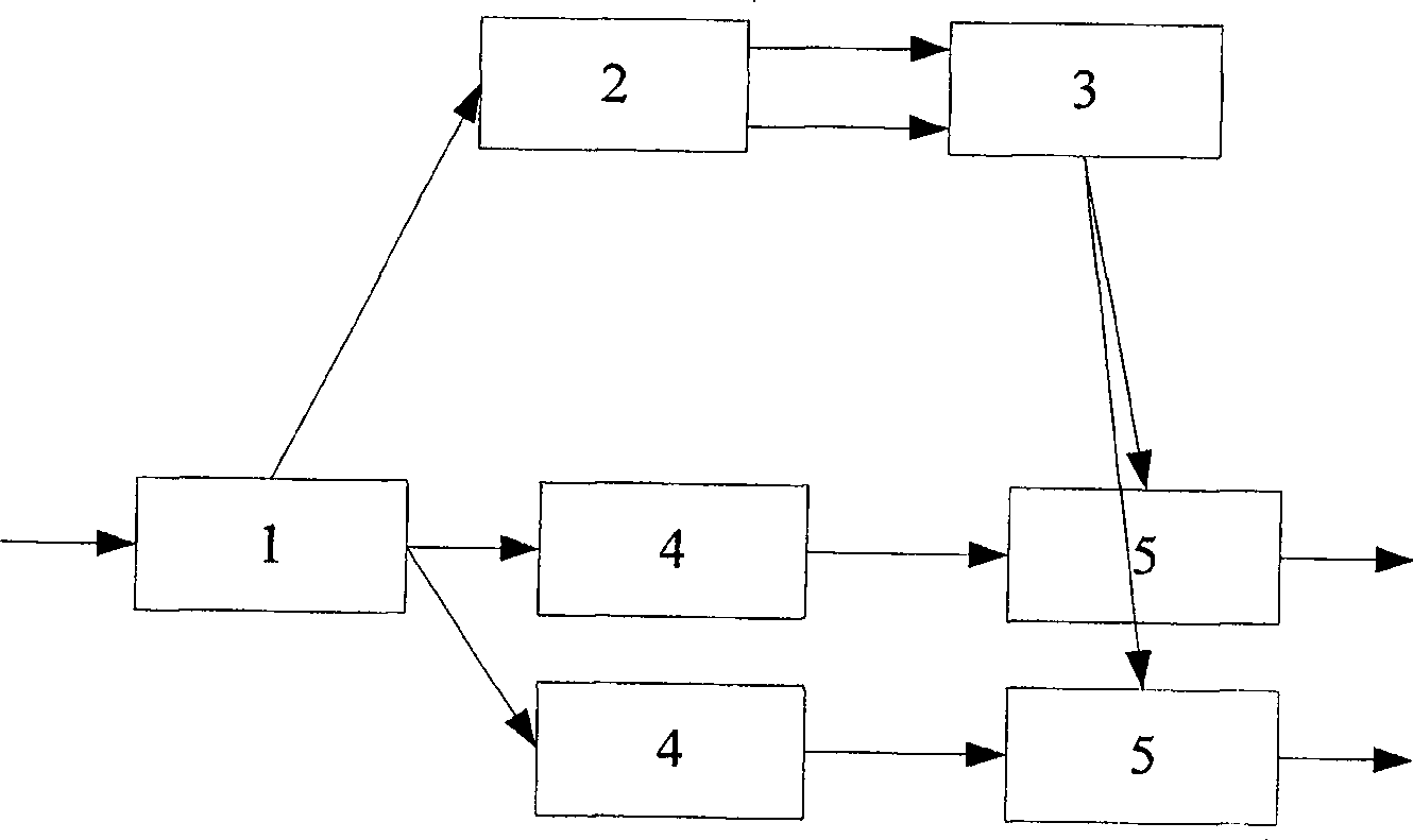
[0035] Such as figure 2 As shown, the optical routing device mainly consists of a light splitting device 1 , a photoelectric conversion and clock extraction device 2 , a routing logic control module 3 , a photoelectric synchronization device 4 and an optical routing module 5 . The optical signal enters the routing device through the optical splitting device 1 and is divided into two routes, one route enters each photoelectric synchronization device 4 , and the other route enters the photoelectric conversion and clock extraction device 2 . The photoelectric conversion and clock extraction device 2 converts optical signals into electrica...


PUM


Abstract

The invention relates to an optical routing device based on address control, which belongs to the technical field of optical routing devices, and is characterized in that it includes: a splitting device, which divides an optical message into two paths; The text is converted into a telegram and the corresponding clock signal; the routing logic control module extracts the address from the received telegram, and generates the control signals of each optical path according to the address mapping relationship of the device; the photoelectric synchronization device receives the optical splitting device Another optical message, by controlling the length of the optical fiber, the optical message is synchronized with the control signal entering the optical channel; the optical routing module is controlled by the control signal generated by the routing logic control module, when the address does not belong to the current channel direction When the port is used, the optical signal is refracted to other places, otherwise the optical signal can pass through smoothly. The invention has the advantages of saving carrier wavelength resources, avoiding data errors, simple structure and fast route selection.

Description

technical field [0001] The invention relates to an optical routing device, and in particular to an IP routing system based on Internet Protocol. Background technique [0002] In the Internet, the networks of various countries and regions are connected through routers, which are the core equipment of the entire Internet. In recent years, with the emergence and application of voice and image services in the Internet, the Internet traffic is increasing at an exponential rate, which puts forward new requirements for the existing network bandwidth. [0003] The working principle of the current core router is: first convert the optical message signal into a telegram signal, and select the route for the telegram signal by searching the local routing table. After the routing is completed, the switch structure in the router distributes the telegram signal to For different output ports, the electro-optic conversion module converts the telegram signal into an optical telegram signal, ...

Claims


Application Information

Patent Timeline
Patent Type & Authority Patents(China)
IPC IPC(8): H04L12/56H04B10/12H04L12/28H04L47/41
Inventor 张小平吴建平张闰华何中敏
Owner TSINGHUA UNIV
Why Eureka
Eureka Blog
Learn More