Connector

A connector and electrical connection technology, applied in the direction of connection, electrical components, coupling devices, etc., can solve the problems of larger size and larger dedicated area for connectors

Inactive Publication Date: 2009-07-15
JST MFG CO LTD
View PDF6 Cites 0 Cited by
  • Summary
  • Abstract
  • Description
  • Claims
  • Application Information

AI Technical Summary

Problems solved by technology

[0004] However, when the above-mentioned locking jig is used, since the soldering portion is provided, the overall size of the connector becomes large, and the area dedicated to the connector on the wiring board becomes large.

Method used


Image

  • Connector
  • Connector
  • Connector

Examples


Embodiment Construction

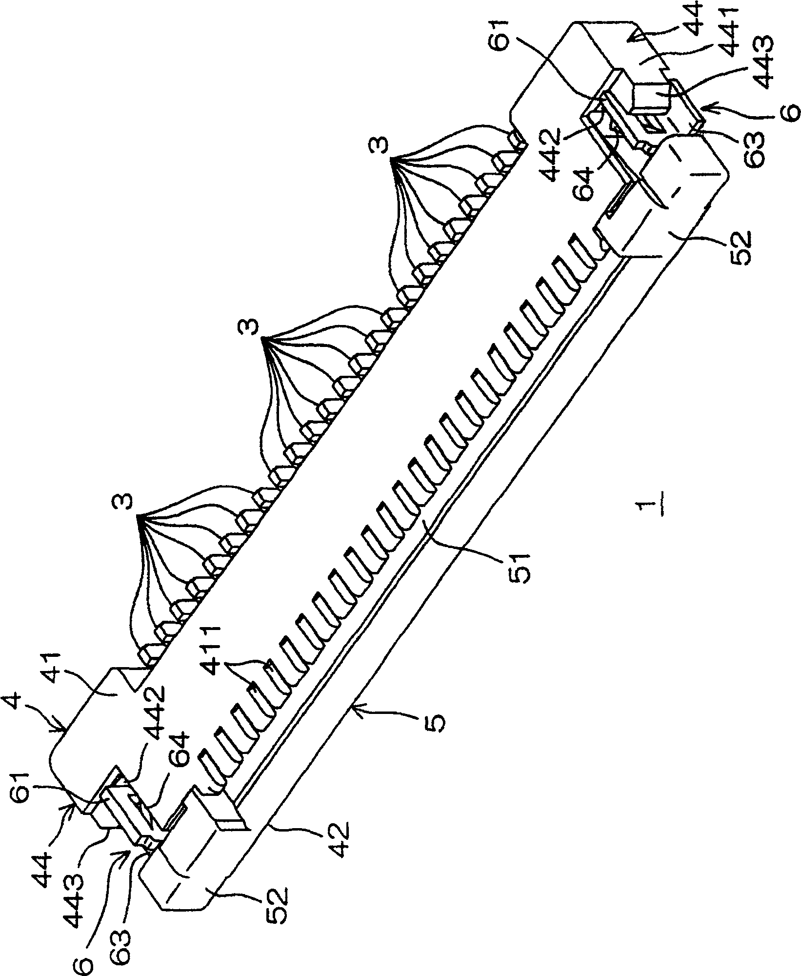
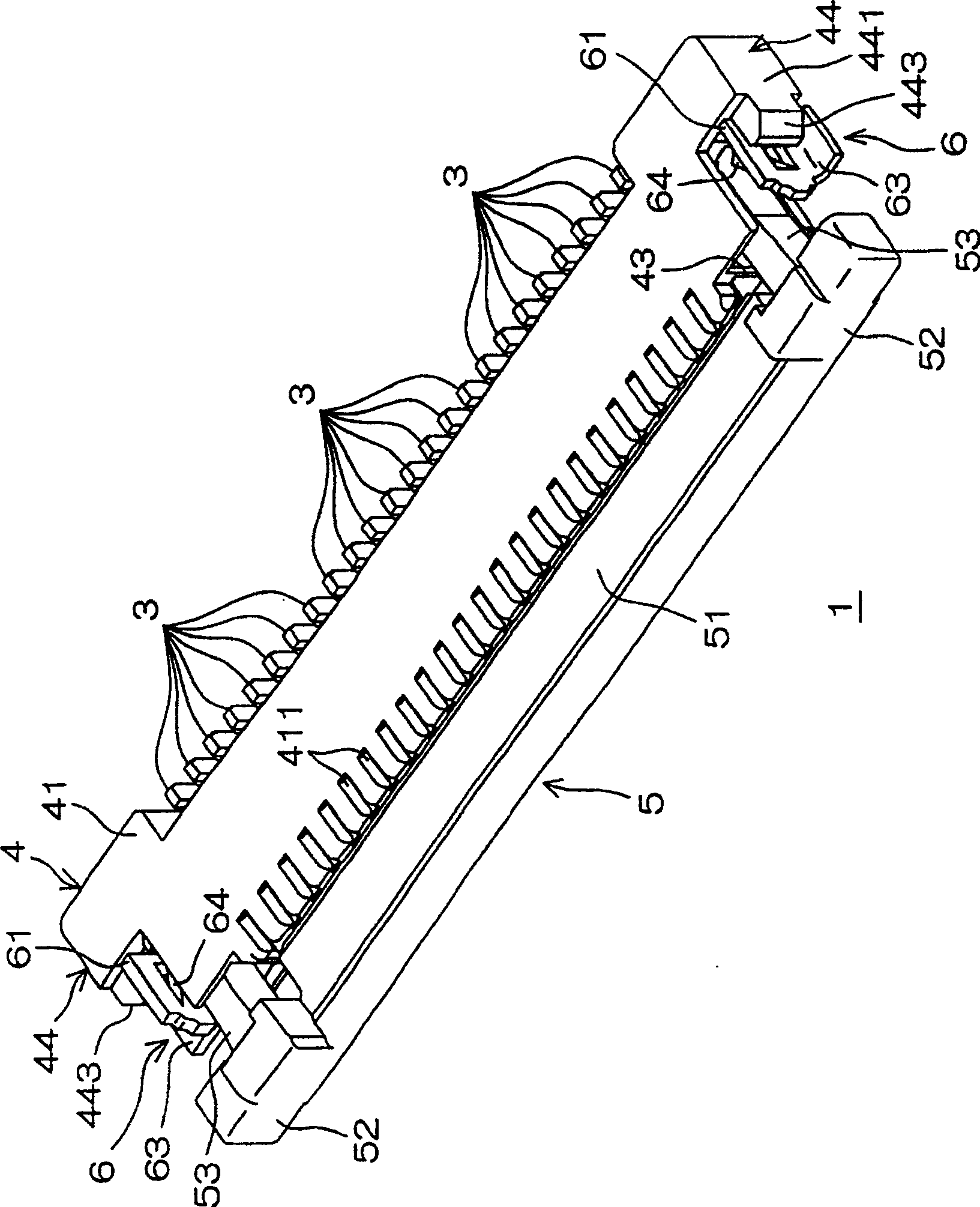
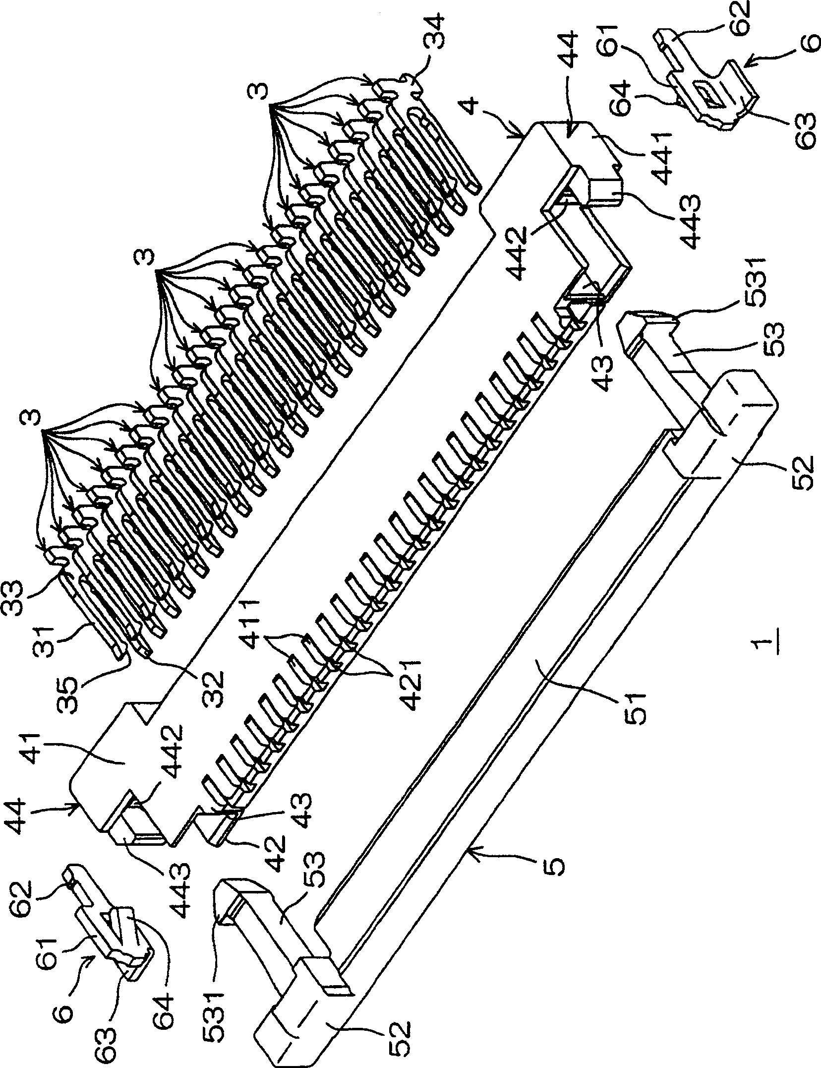
[0015] figure 1 and figure 2 It is a perspective view showing the structure of the connector which concerns on one Embodiment of this invention. in addition, image 3 yes figure 1 An exploded perspective view of the connector shown. This connector 1 is mounted on a wiring board (not shown) and is used to connect an FPC (Flexible Printed Circuit: flexible printed circuit) 2 (refer to Image 6 ) are electrically connected to the wiring substrate. In addition, the connector 1 includes a plurality of metal contacts 3, a resin case 4 holding the contacts 3, and a slidable front-rear direction relative to the case 4 for connecting the plurality of contacts. 3 Push the resin slider 5 of the FPC 2 and the metal reinforcing plate 6 for strengthening the connection of the plurality of contacts 3 to the wiring board.

[0016] The contact 3 is formed, for example, by punching a metal plate, and has an elastic piece 31 and a fixed piece 32 facing each other, a root 33 connecting the...


PUM


Abstract

PROBLEM TO BE SOLVED: To provide a connector capable of preventing increase in an occupied area on a wiring substrate while being provided with a fixed part such as a soldering part. SOLUTION: The connector 1 is provided with a plurality of metallic contacts 3, a resin housing 4 to retain those contacts 3, and a metallic reinforcement tab 6 to reinforce connection of the plurality of contacts 3 with the wiring substrate. The reinforcement tab 6 is provided with the plate-shaped tab body 61 crossing orthogonally to the width direction, and the soldering part 63 as the rectangle plate shaped-fixed part which is bent toward the width direction outside from the lower end edge of the tab body 61, and extends toward the width direction outside. Then, the width direction outside end edge of the respective soldering parts 63 is positioned in the width direction more inside than the both width direction outside faces of the housing 4. COPYRIGHT: (C)2006,JPO&NCIPI

Description

technical field [0001] The present invention relates to a connector for connecting flat and thin electrical connection members such as FPC (Flexible Printed Circuit) and FFC (Flexible Flat Cable) to a wiring board. Background technique [0002] There is known a connector mounted on a wiring board for connecting a flat and thin electrical connection member such as an FPC to the wiring board. This type of connector is provided with: a housing holding a plurality of contacts, a slider for pushing the flexible wiring board to the contacts provided slidably relative to the housing, and a position for applying a pushing force to the flexible wiring board ( pushed into the housing) to hold the slider's locking mechanism. [0003] In such a connector for FPC, it is proposed that a locking mechanism is constituted by a locking jig having a soldered portion soldered to a wiring board and an elastically deformable engaging piece engaged with a slider (for example, Refer to Japanese P...

Claims


Application Information

Patent Timeline
Patent Type & Authority Patents(China)
IPC IPC(8): H01R12/28H01R12/79
Inventor 知览清彦村上阳一川口龙二
Owner JST MFG CO LTD
Why Eureka
Try Eureka