
Shaped-steel concrete frame-steel supporting structure type steel column preconstraint node

A steel support and concrete technology, applied in building structure, construction and other directions, can solve the problems of tension between steel bars and steel bars, difficult anchoring of steel bars, dense steel bars, etc. Effect

Active Publication Date: 2009-06-24
BEIJING URBAN CONSTR DESIGN & DEV GRP CO +1
View PDF6 Cites 0 Cited by
  • Summary
  • Abstract
  • Description
  • Claims
  • Application Information

AI Technical Summary

Problems solved by technology

[0005] The purpose of the present invention is to design a steel concrete frame-steel support structure steel column top constraint node, to solve the problem of reliable and safe connection between the support of the large-span space roof structure and the steel column top; Concentrated steel bars, too many interspersed steel bars, tense space conflicts between steel bars and section steel, and difficult anchoring of steel bars

Method used


Image

  • Shaped-steel concrete frame-steel supporting structure type steel column preconstraint node
  • Shaped-steel concrete frame-steel supporting structure type steel column preconstraint node
  • Shaped-steel concrete frame-steel supporting structure type steel column preconstraint node

Examples


Embodiment Construction

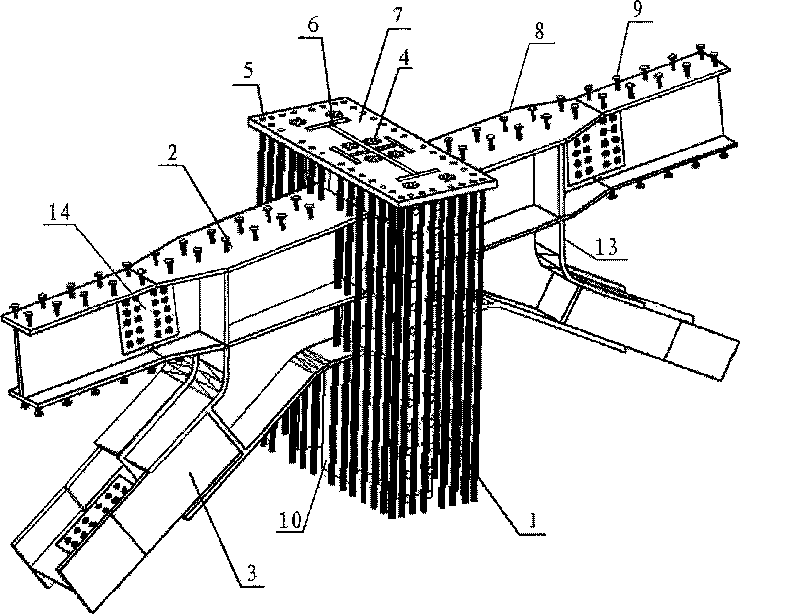
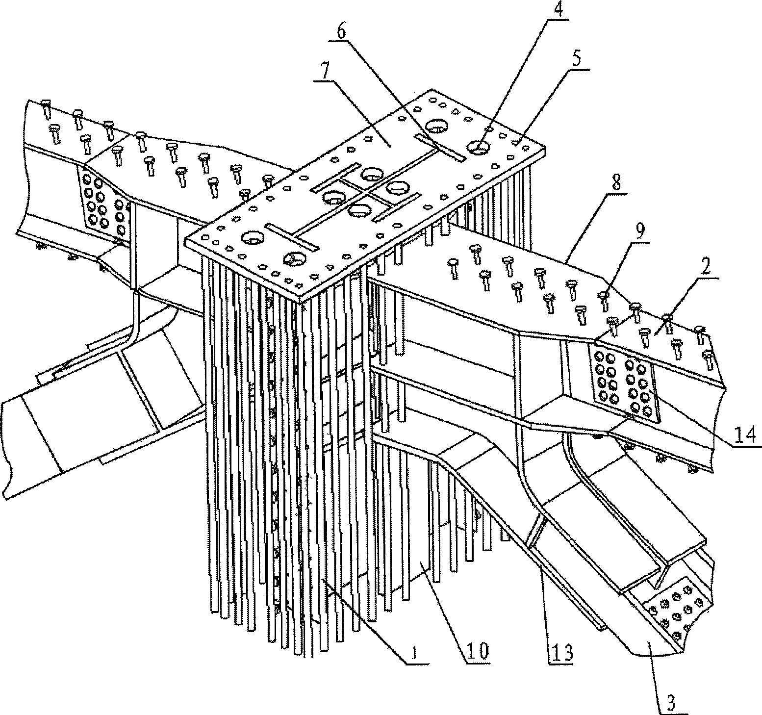
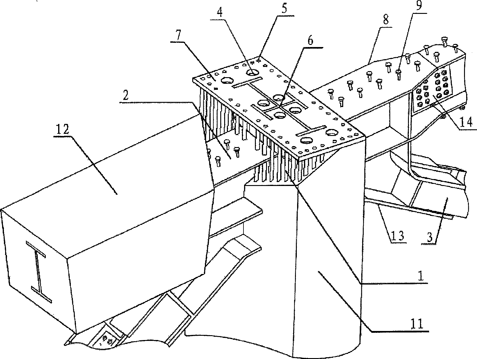
[0027] Examples see Figure 1-3 As shown, this type of steel concrete frame-steel support structure steel column top constrained joint, consists of beams of medium

[0028] Steel 2, column medium steel 10, column main reinforcement 1, steel support 3, column concrete 11, and beam concrete 12 are handed over and poured into one, which is characterized in that a restraint anchor is welded on the top of column medium steel 10 and column main reinforcement 1 The steel plate 7 has a vibrating hole 4 and a welding line hole 6 in the middle of the restraint anchor steel plate 7, and is welded with the section steel to form a weld line in the factory. A plug welding hole 5 is opened on the edge of the restraint anchor steel plate 7, and the main reinforcement of the column 1 and the The restraint anchor steel plate 7 is welded at the plug welding hole 5, and the column mid-section steel 10 is welded with the restraint anchor steel plate 7 at the weld line hole. The main reinforcement...


PUM


Abstract

A steel-concrete frame-steel support structure-shaped steel column top restraint joint, which is composed of beam medium steel, column medium steel, column main reinforcement, steel support, column concrete, and beam medium concrete are handed over and poured into one, and the column medium steel and column main reinforcement A constrained anchor steel plate is welded on the top of the constrained anchor plate, with a vibrating hole and a welding line hole in the middle of the constrained anchor plate, and a plug weld hole is opened at the edge of the constrained anchor plate, the main reinforcement of the column and the constrained anchor plate are welded at the plug weld, and the column The medium-sized steel and the restraint anchor steel plate are welded at the welding line hole. It solves the problem of reliable and safe connection between the support of the long-span steel roof and the top of the steel column, and improves the integrity of the joints at the top of the steel column. On the one hand, it saves the amount of anchoring steel bars, and on the other hand, it facilitates construction and improves construction efficiency. Save labor and time.

Description

(1) Technical field [0001] The invention relates to an anti-seismic node structure in a steel-concrete composite structure. (2) Background technology [0002] The National Gymnasium is one of the three main venues for the Beijing 2008 Olympic Games. During the Olympic Games, gymnastics competitions and handball finals will be held mainly, and wheelchair basketball competitions will be held during the Paralympic Games. Its building consists of a competition hall and a warm-up hall. The competition hall can accommodate about 19,000 spectators, with a total construction area of ​​80,890m 2 , one basement and four floors above ground. The longitudinal length of the roof plane projection is 195.5m, and the horizontal width is 114m. In this complex spatial structure system, the design of the connection node between the long-span structure and the lower main structure and its adjacent area is extremely critical and important. This node is an important part that supports the long-...

Claims


Application Information

Patent Timeline
Patent Type & Authority Patents(China)
IPC IPC(8): E04B1/19E04B1/30E04B1/58
Inventor 陈金科覃阳冯阳杨铮许硕陈奕曾莉荣
Owner BEIJING URBAN CONSTR DESIGN & DEV GRP CO
Learn More