
Automotive engine hood

A technology for engine hoods and motor vehicles, which is applied to vehicle parts, upper structures, upper structure sub-assemblies, etc., which can solve the problems of increased elastic deformation of the outer panel 122 and inability to ensure the tension and rigidity of the engine hood, and achieve excellent protection performance , HIC value reduction effect

Active Publication Date: 2009-06-24
KOBE STEEL LTD
View PDF8 Cites 0 Cited by
  • Summary
  • Abstract
  • Description
  • Claims
  • Application Information

AI Technical Summary

Problems solved by technology

But when Figure 14 In the shown corrugated bead 129, when only the inclination angle α of the inclined surface 129a is reduced, the joint positions of the outer panels at both ends of the inner panel are far from the peripheral edge of the outer panel, and the tension rigidity of the motor vehicle hood cannot be ensured. The amount of elastic deformation of the outer panel 122 increases

Method used


Image

  • Automotive engine hood
  • Automotive engine hood
  • Automotive engine hood

Examples


no. 1 approach

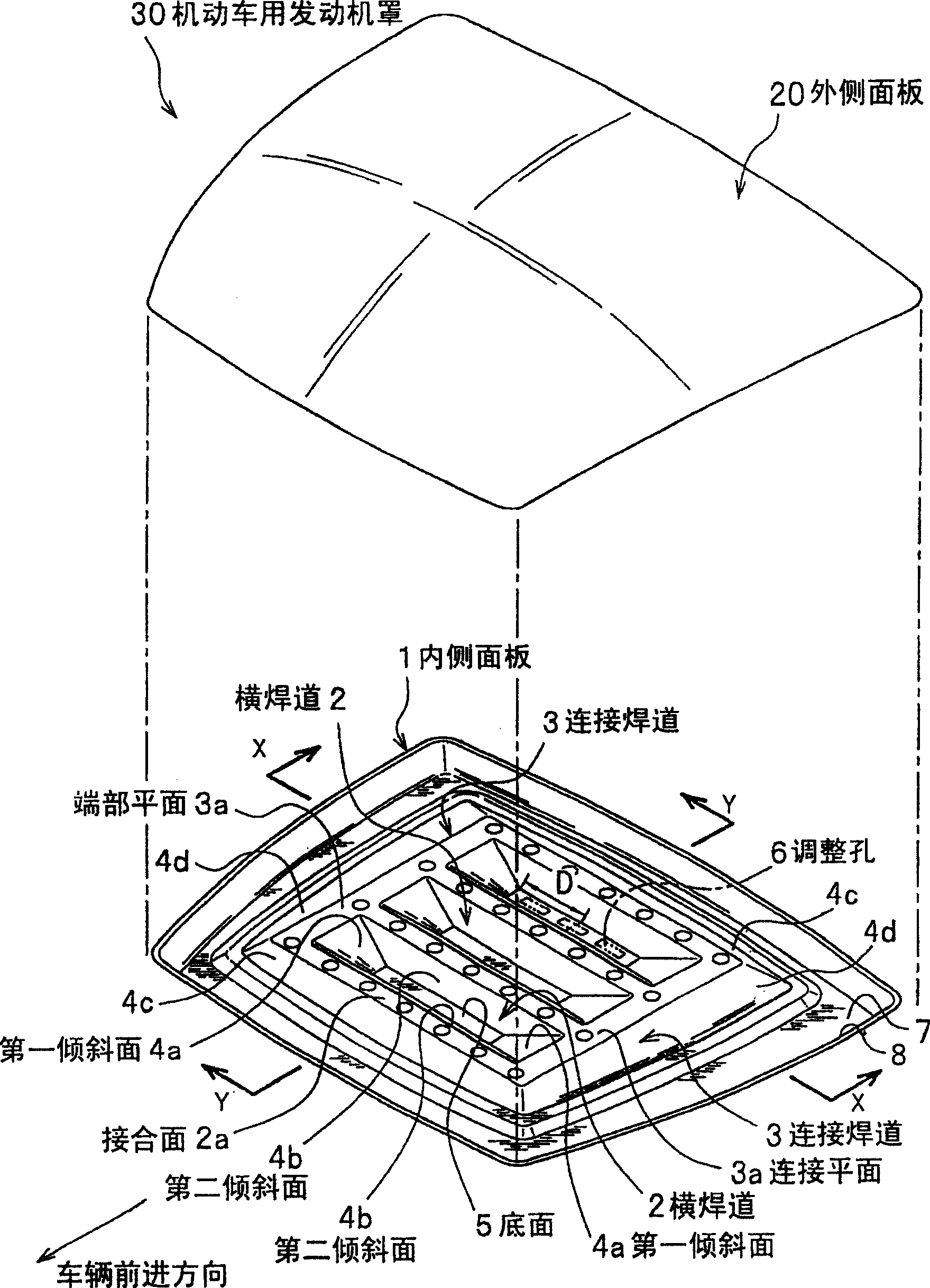
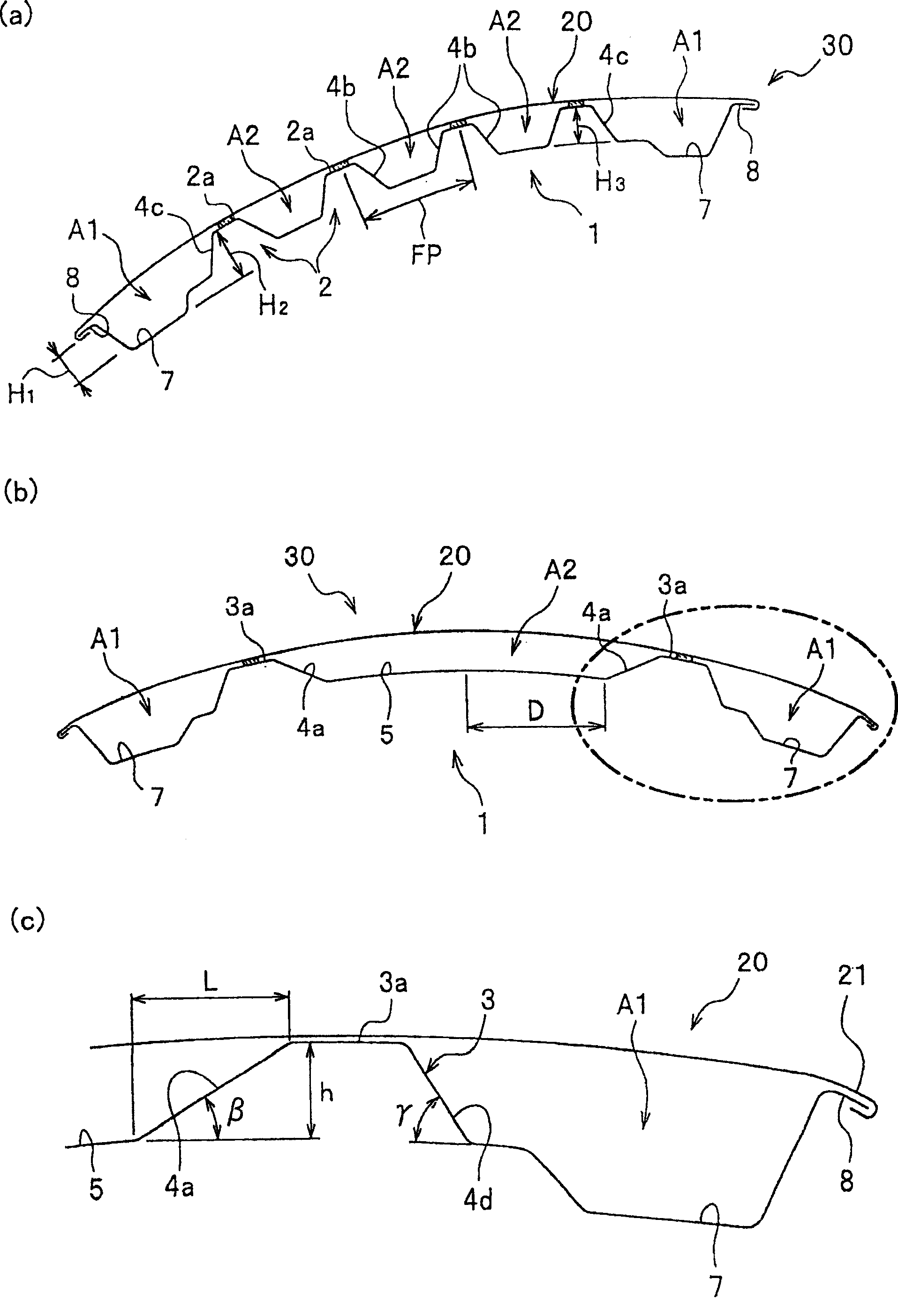
[0049] Such as figure 1 and figure 2 As shown, the motor vehicle hood 30 is formed in a cross-sectional structure in which the outer panel 20 and the inner panel 1 are joined, and the two panels 20, 1 are joined to form spaces A1, A2 between the two panels.

[0050] (outside panel)

[0051] Such as figure 1 As shown, the outer panel 20 is formed in a planar shape, or is made of a light-weight, high-tensile metal plate having a predetermined curvature, and the raw material metal is preferably steel, or an aluminum alloy of 3000, 5000, 6000, or 7000. The thickness of the outer panel 20 is preferably, for example, a steel plate of 1.1 mm or less, and an aluminum alloy plate of 1.5 mm or less. In addition, the outer panel 20 may be made of resin or a carbon fiber plate. In addition, the outer panel 20 is joined at its peripheral edge to the peripheral edge of the inner panel 1 described later by fitting, bonding, brazing, etc. by hemming, and between the outer panel 20 and ...

no. 2 approach

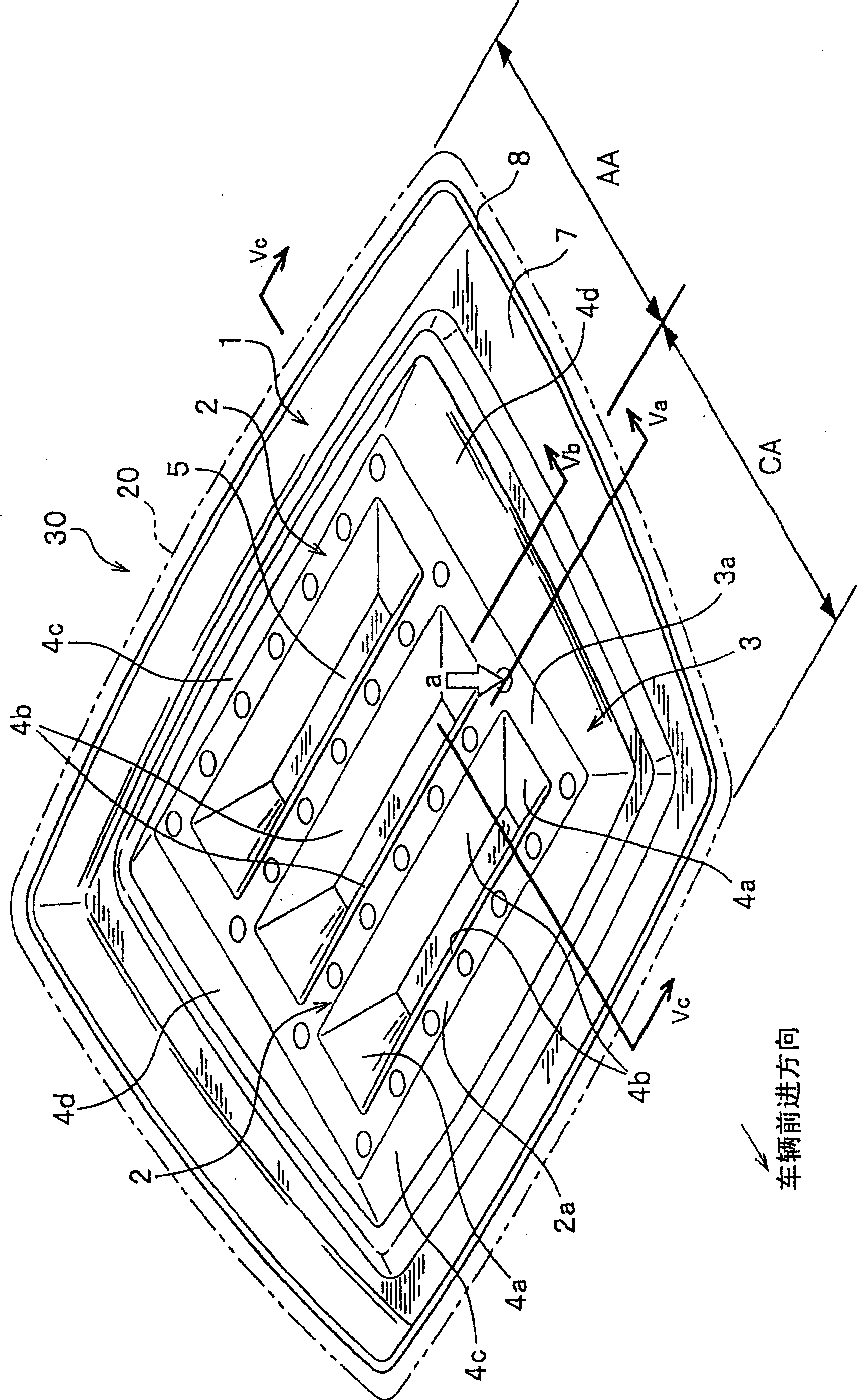
[0080] Next, a second embodiment of the present invention will be described. exist Figure 1 to Figure 6 In , the case where the inner panel 1 is used as the transverse weld bead 2 perpendicular to the direction of travel of the vehicle is described, but as Figure 7 As shown, it may be configured as a longitudinal bead 12 in a direction substantially parallel to the vehicle advancing direction. Figure 7 (a) and (b) are a perspective view and a cross-sectional view showing an inner panel of a motor vehicle hood according to a second embodiment; Figure 8 (a), (b) is a perspective view which shows the application example of the inner panel of the motor vehicle bonnet concerning 2nd Embodiment. In addition, since the structure which has already been demonstrated with the horizontal bead differs only in the direction, since it achieves substantially the same function, the same code|symbol is attached|subjected and the description is abbreviate|omitted.

[0081] Inner panel 11...


PUM


Abstract

An automotive engine hood is built by joining together respective edge parts of an outer panel and an inner panel such that spaces are formed between the outer and the inner panel. The inner panel has a plurality of ridge-like beads and ridge-like connecting beads connecting at least end parts of the beads on one of the opposite sides of the beads with respect to length of the beads. Each of the connecting beads has a top wall having a connecting surface continuous with the joint surfaces of the top walls of the beads, and a first inclined surface extending from the connecting surface to a bottom surface surrounded by the adjacent ones of the beads and the connecting beads. The automotive engine hood meets in equalities: 1.5h < L and L < D, where L is distance between a boundary between the connecting surface and the first inclined surface, and a boundary between the first inclined surface and the bottom surface along the surface of the inner panel, h is height of the connecting surface from the bottom surface, and D is distance between one of the opposite ends of the bottom surface and a middle part of the bottom surface.

Description

technical field [0001] The present invention relates to a motor vehicle hood that is used by joining an outer panel and an inner panel, and particularly relates to a motor vehicle hood excellent in energy absorption at the time of a collision. Background technique [0002] In recent years, the protection of pedestrians in motor vehicle accidents has been regulated, and pedestrian protection performance has also attracted attention as a calibration index for motor vehicle hoods. On the other hand, as motor vehicle engines increase in size due to higher output, and the number of mounting members in the engine room increases due to multifunctionalization, the space under the hood required to protect pedestrians becomes smaller. Therefore, it is important to develop a motor vehicle hood capable of efficiently absorbing collision energy in a small space in order to achieve both a sporty design and a pedestrian protection performance. [0003] As a motor vehicle hood that satisfi...

Claims


Application Information

Patent Timeline
Patent Type & Authority Patents(China)
IPC IPC(8): B62D25/10
Inventor 石飞秀树
Owner KOBE STEEL LTD
Learn More