
Auxiliary switch

An auxiliary switch and thick shaft technology, applied in electrical switches, electrical components, circuits, etc., can solve the problems of thinning cam walls, occupying a lot of thickness space, poor mechanical strength of plastic cams, etc., to reduce the overall size and volume. , the effect of compact structure

Active Publication Date: 2009-06-03
CHENGDU RELIANCE ELECTRIC
View PDF7 Cites 0 Cited by
  • Summary
  • Abstract
  • Description
  • Claims
  • Application Information

AI Technical Summary

Problems solved by technology

At present, there are two kinds of auxiliary switches, one is not equipped with a rotating shaft, such as the universal transfer switch disclosed in the Chinese invention patent specification CN200510039139.8, which is directly driven by a splined cam made of plastic material, and its disadvantage is that the mechanical strength of the plastic cam is poor. , transmission is poor, and there are timing errors, especially not suitable for auxiliary switches with a high number of nodes; currently known another auxiliary switch, such as the universal transfer switch disclosed in my country's utility model patent specification CN200420032370.5, although a rotating shaft (the The patent defines it as a camshaft), but because the set rotating shaft is an equal thick axis, it is only suitable for manual manipulation, it is not convenient to directly connect the auxiliary switch with the operating mechanism of the control device, and automatic control cannot be realized, and the equal thick axis Use will increase the overall volume of the auxiliary switch, or make the cam wall thinner, which will easily cause a short circuit between poles
At the same time, the bases used by the known auxiliary switches are not equipped with reinforcement columns. During use, the bases are easily deformed, especially the movable contact seat chute on the base is easily deformed, causing the movable contact seat to be easily stuck. Dead in the chute on the base, causing electrical failure
In addition, the prior art uses wiring board components as the wiring device, and its disadvantages are that the wiring efficiency is low and the space occupied by the thickness is large.

Method used


Image

  • Auxiliary switch
  • Auxiliary switch
  • Auxiliary switch

Examples


Embodiment approach

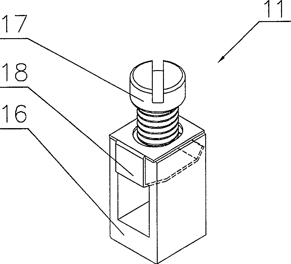
[0028] Such as Figure 1-6As shown, the first specific embodiment of the present invention is: an auxiliary switch, including a rotating shaft 1, a cover plate 2, a connecting bolt 3, a pull rod 4 and a multi-layer contact assembly 5, and each layer of contact assembly 5 includes a base 6 , moving contact 7, moving contact seat 8, static contact 9, spring 10, wiring device 11 and cam 12, wherein rotating shaft 1 is divided into thick shaft 13 and thin shaft 14 two parts, in thick shaft 13 and thin shaft A limiting seat 15 is provided on the thick shaft 13 at the junction of 14 . There are four wiring devices 11 in each contact assembly 5 , and each wiring device 11 is composed of a crimping frame 16 and a screw 17 , and a lifting piece 18 is also provided between the crimping frame 16 and the screw 17 . The thick shaft 13 and the thin shaft 14 are two metal shafts with different thicknesses. In this embodiment, square shafts (i.e. quadrilateral shafts) are used. One end of th...


PUM


Abstract

The invention discloses an auxiliary switch, which includes a rotary shaft (1), a cover (2), a connection bolt (3), a pull rod (4), and a multi-layer contact component (5). Each layer of contact component (5) includes a base (6), a moving contact (7), a moving contact base (8), a static contact (9), a spring (10), a wiring device (11), and a cam (12). The rotary shaft (1) is divided into a thick shaft (13) and a thin shaft (14), both of which are of polygon. A limiting base (15) is arranged on the thick shaft (13) at the connection of the thick shaft (13) and the thin shaft (14). The wiring device (11) is composed of a tension frame (16) and a bolt (17). The invention has the advantages of small cubage, small thickness, multiple layers, concise structure, convenient wiring, and automatic operation.

Description

technical field [0001] The invention relates to a switching device used in an electrical device, in particular to an auxiliary switch (also known as a universal transfer switch or a cam switch) used in an electrical control circuit, which belongs to the technical field of electrical appliances. Background technique [0002] The auxiliary switch generally includes a transmission mechanism, a tensioning mechanism and a multi-layer contact assembly, and each layer of contact assembly includes a base, a contact part, a wiring device and a cam. At present, there are two kinds of auxiliary switches, one is not equipped with a rotating shaft, such as the universal transfer switch disclosed in the Chinese invention patent specification CN200510039139.8, which is directly driven by a splined cam made of plastic material, and its disadvantage is that the mechanical strength of the plastic cam is poor. , transmission is poor, and there are timing errors, especially not suitable for auxi...

Claims


Application Information

Patent Timeline
Patent Type & Authority Patents(China)
IPC IPC(8): H01H19/62H01H3/42
Inventor 任志昊李正强
Owner CHENGDU RELIANCE ELECTRIC
Learn More