Eureka AIR delivers breakthrough ideas for toughest innovation challenges, trusted by R&D personnel around the world.

Production method of film laminates and production apparatus used therein

A manufacturing method and a manufacturing device technology, which are applied in the fields of optical thin films and image display devices, can solve the problems of reduced attraction, narrowing the suction interval of suction nozzles, complex structure, etc., and achieve the effect of improving attraction

Active Publication Date: 2009-06-03
NITTO DENKO CORP
View PDF9 Cites 6 Cited by
  • Summary
  • Abstract
  • Description
  • Claims
  • Application Information

AI Technical Summary

Problems solved by technology

[0006] However, since the water supply nozzle is arranged in the suction nozzle, its structure is complicated. When cleaning or repairing the water supply nozzle, it is necessary to put a cleaning tool into the suction nozzle, or to extract the water supply nozzle to the outside of the suction nozzle
Therefore, the operation is cumbersome
[0007] In addition, by installing a water supply nozzle in the suction nozzle, there is also a problem that the suction space in the suction nozzle is reduced, and the suction force is reduced.
Furthermore, the water flowing out from the water supply nozzle interferes with the adhesive liquid sucked inside the suction nozzle, so that the suction cannot be performed smoothly.
[0008] In addition, as mentioned above, the problem that occurs when air is sprayed from the end is not limited to the above-mentioned method of Patent Document 1 in which a protective film is bonded to both sides of the polarizer, but also occurs when both sides are bonded by the conventional method.

Method used


Image

  • Production method of film laminates and production apparatus used therein
  • Production method of film laminates and production apparatus used therein
  • Production method of film laminates and production apparatus used therein

Examples


Embodiment Construction

[0055] Refer to the side below Figure 1 to Figure 5 , one embodiment of the present invention will be described. However, parts that are not necessary for the description are omitted, and there are also parts that are shown enlarged or reduced in order to facilitate the description.

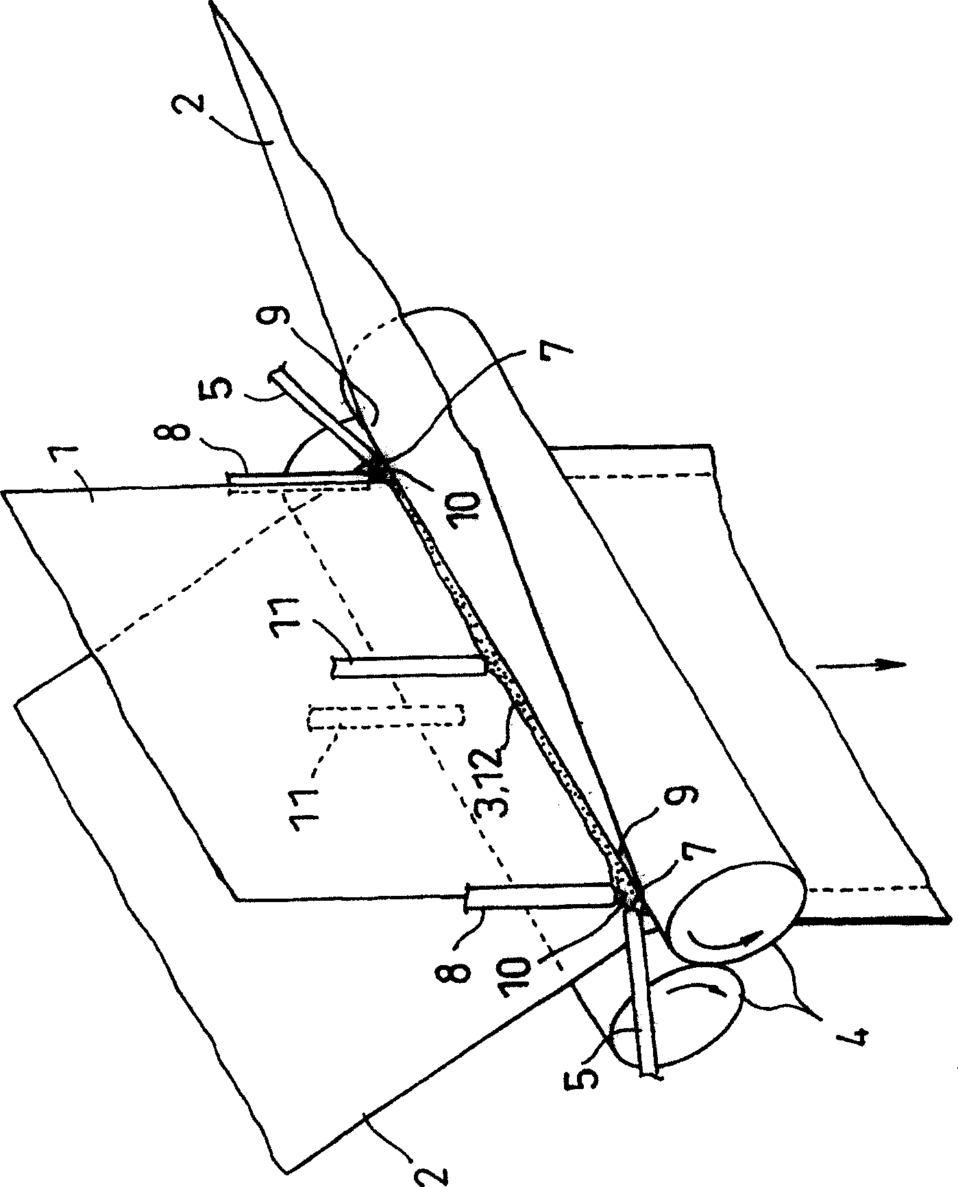
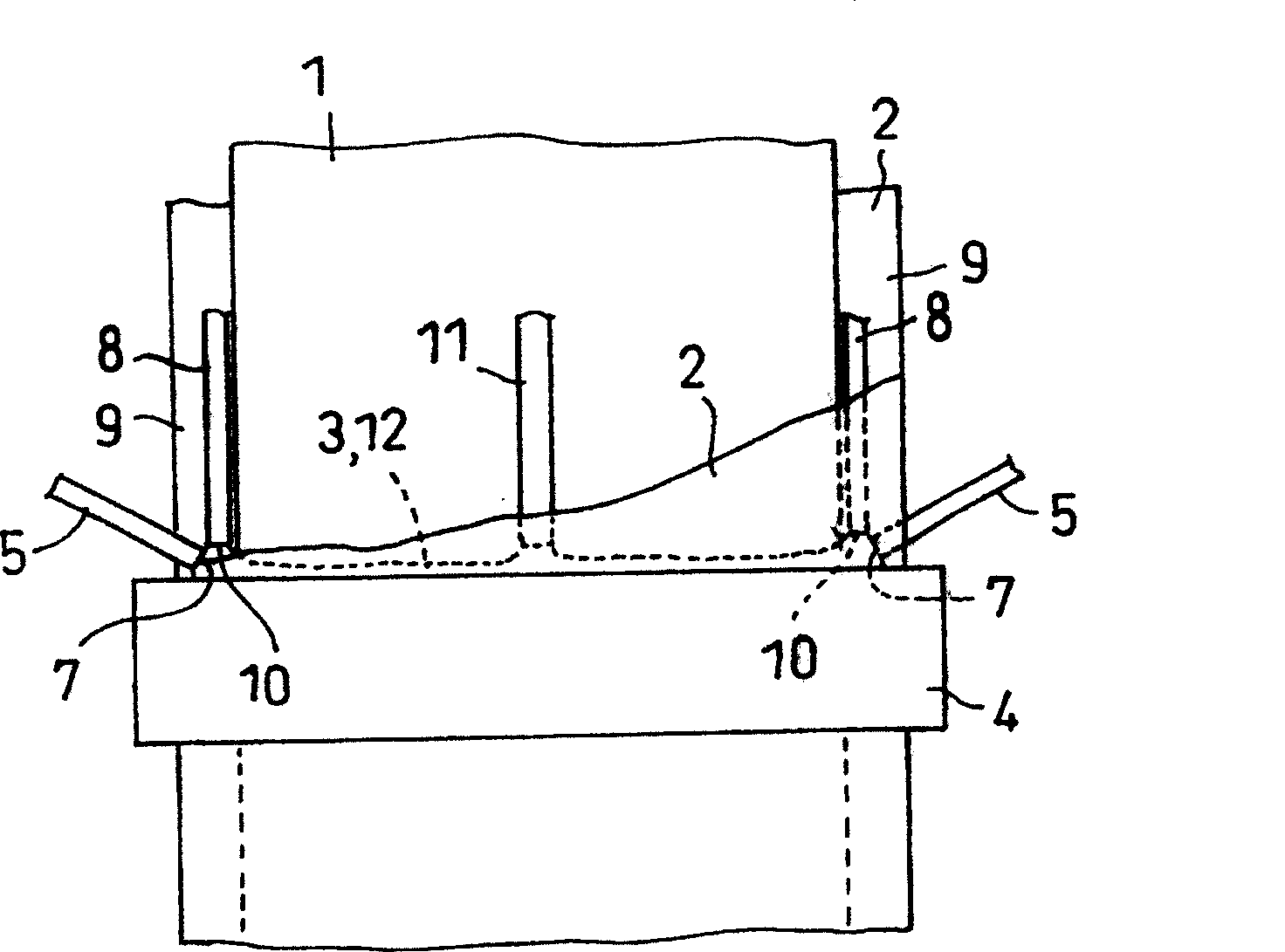
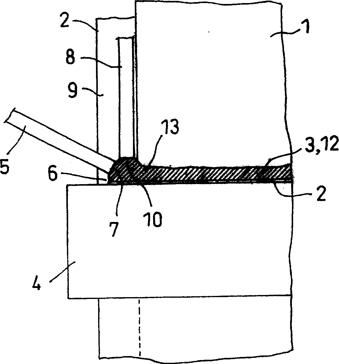
[0056] First, the method for producing the film laminate in the present invention will be described below using a polarizing plate as an example. figure 1 It is a perspective view for demonstrating the manufacturing method of the polarizing plate in embodiment of this invention. figure 2 It is a side view for demonstrating the manufacturing method of the said polarizing plate. image 3 is to zoom in figure 2 An enlarged view of the main part of . Figure 4 It is a schematic diagram showing the shape of the opening portion of the suction port in the suction nozzle in the above-mentioned manufacturing apparatus of the polarizing plate. Figure 5 It is a cross-sectional schematic view schema...


PUM

PropertyMeasurementUnit
viscosityaaaaaaaaaa
thicknessaaaaaaaaaa
degree of polymerizationaaaaaaaaaa

Abstract

The manufacturing process relates to a manufacturing of a film laminate in which at least one side of the film 1 is provided with another film 2. The process comprises the steps of arranging the film 2 on at least one side of the film 1, feeding an adhesive liquid to the laminating part of the film 1 and film 2, at the same time feeding a liquid countering the adhesive liquid flowing toward at least one end of the film 1 from at least one end of the film 1 and laminating the film 1 and film 2 by pressing them. To provide a manufacturing process of film laminates by which the leakage of an adhesive liquid from the edge of the laminates in laminating one film to the other is prevented without solidifying the adhesive, a manufacturing apparatus used for the manufacturing process, a film laminate obtained by the manufacturing process and an optical film and an image display device provided with the film.

Description

technical field [0001] The present invention relates to a method for producing a film laminate in which other films are provided on at least one side of the film by means of an adhesive, a production device used in the method, a film laminate obtained by the production method, a film laminate obtained by the method A polarizing plate obtained by the production method, an optical film including the polarizing plate, and an image display device. Background technique [0002] In the past, in the method of laminating films with an adhesive liquid called an adhesive or an adhesive, there was usually a method of laminating after coating the adhesive liquid on the film, or supplying the adhesive liquid to a pair of films A method of bonding between a pair of rollers and the like through a press-bonding mechanism (for example, refer to Patent Document 1). In such lamination, when using a low-viscosity adhesive, there is a problem of contamination of the film and the device due to o...

Claims


Application Information

Patent Timeline
Patent Type & Authority Patents(China)
IPC IPC(8): C08J5/12B32B27/00G02B1/08
CPCB32B27/08B32B37/10B32B37/12G02B1/14G02B5/30
Inventor 八木伸圭龟田祥弘北川博昭中村强
Owner NITTO DENKO CORP
Why Eureka
Eureka Blog
Learn More