
Warp knitting machine

A technology of warp knitting machine and drum, which is applied in the field of warp knitting machine, and can solve problems such as difficult control of yarn guide

Active Publication Date: 2009-04-15
KARL MAYER CHINA
View PDF7 Cites 1 Cited by
  • Summary
  • Abstract
  • Description
  • Claims
  • Application Information

AI Technical Summary

Problems solved by technology

But it is difficult to achieve sufficiently precise yarn guide control at higher operating speeds

Method used


Image

  • Warp knitting machine
  • Warp knitting machine
  • Warp knitting machine

Examples


Embodiment Construction

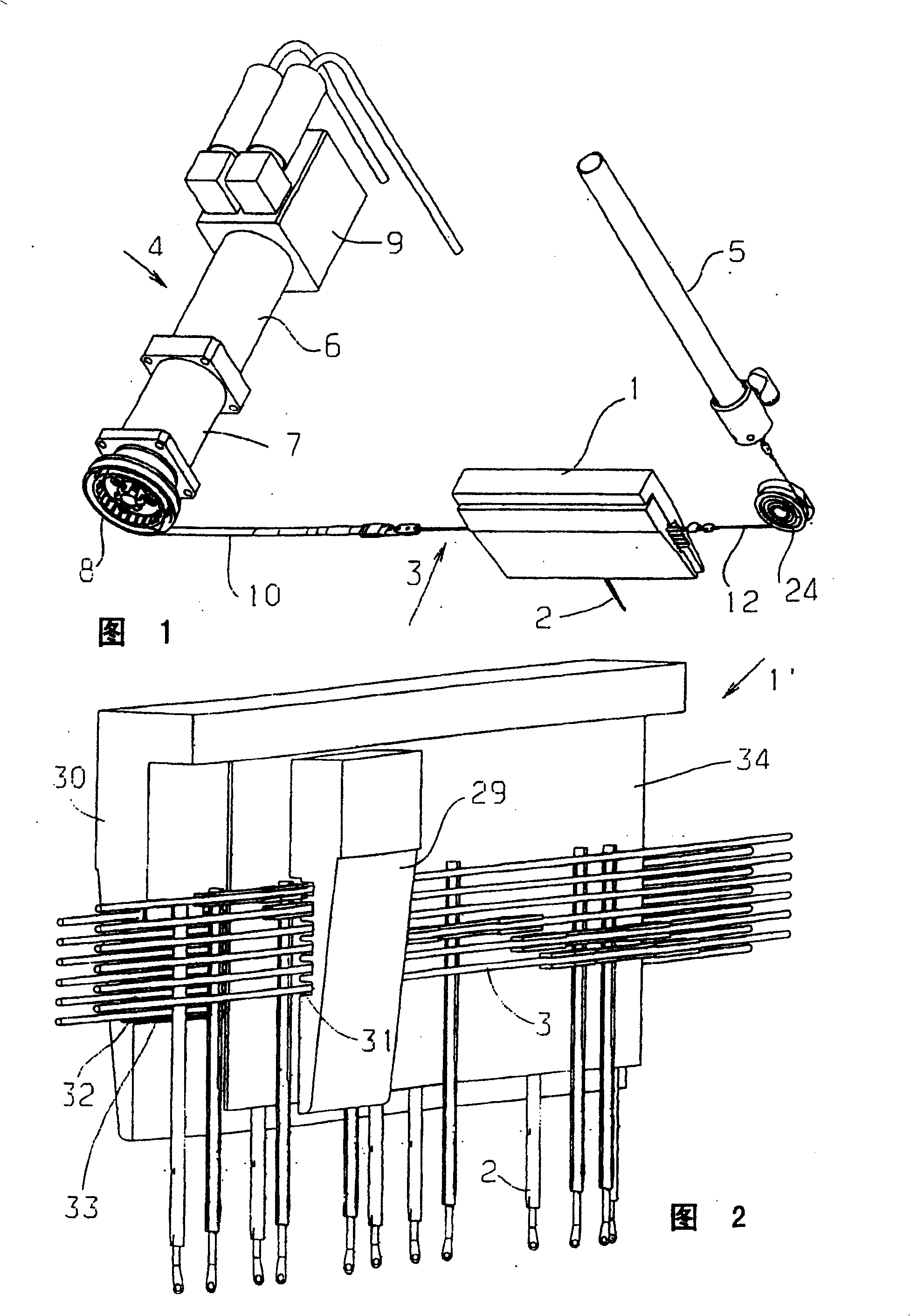
[0034] FIG. 1 schematically shows a flower bar 1 with a thread guide 2 . In practice, the flower bar is much longer and usually also has more than one thread guide 2 . This schematic is chosen for simplicity.

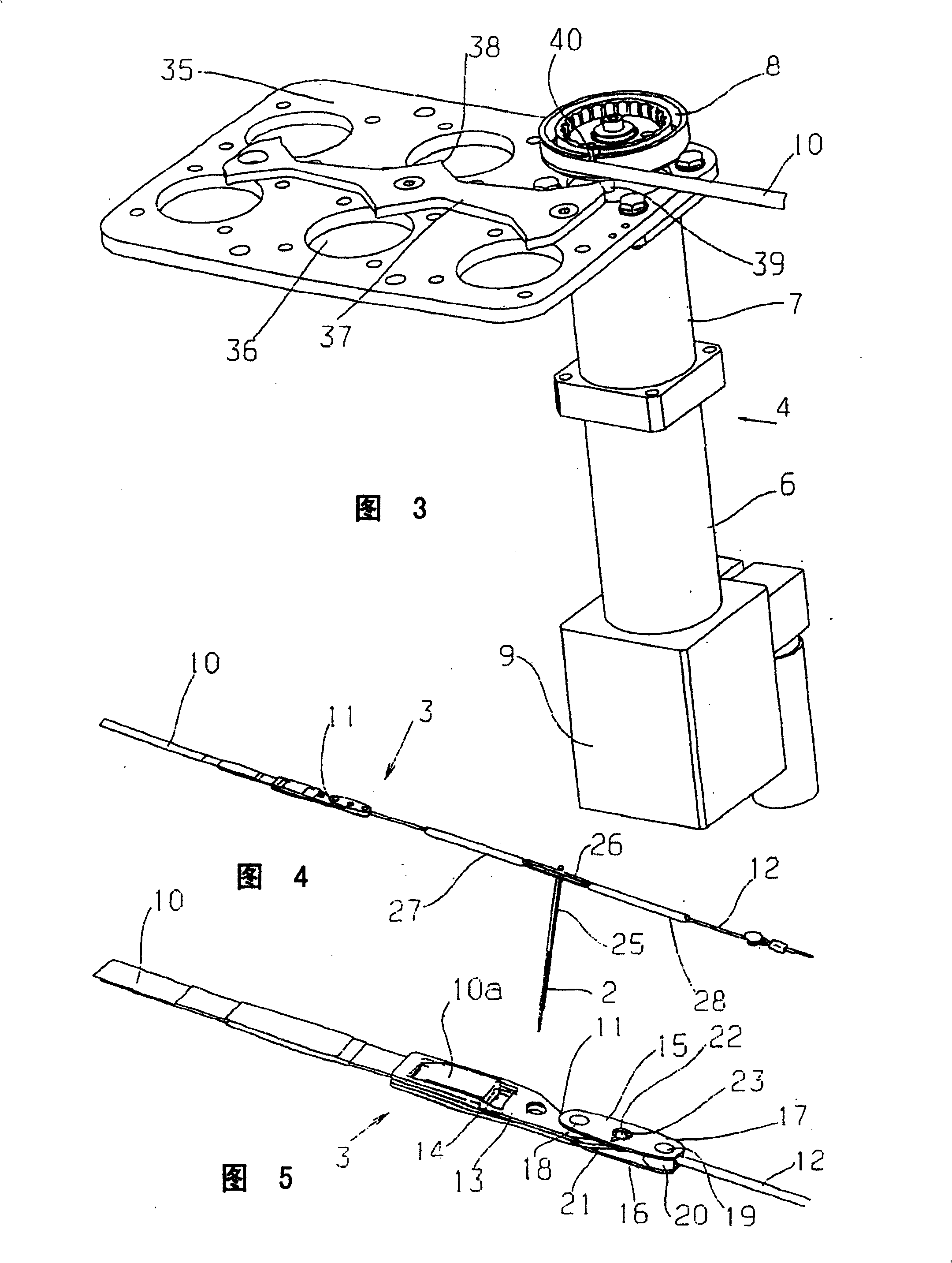
[0035] The yarn guide 2 is fixed on the drawing member 3 . The tensile element 3 is tensioned between the transmission 4 and the tensioning device 5 . The tensioning device 5 produces a constant tension force on the tensioning element 3 independent of the position of the tensioning element 3 . For this purpose, the tensioning device is for example in the form of a compressed air cylinder.

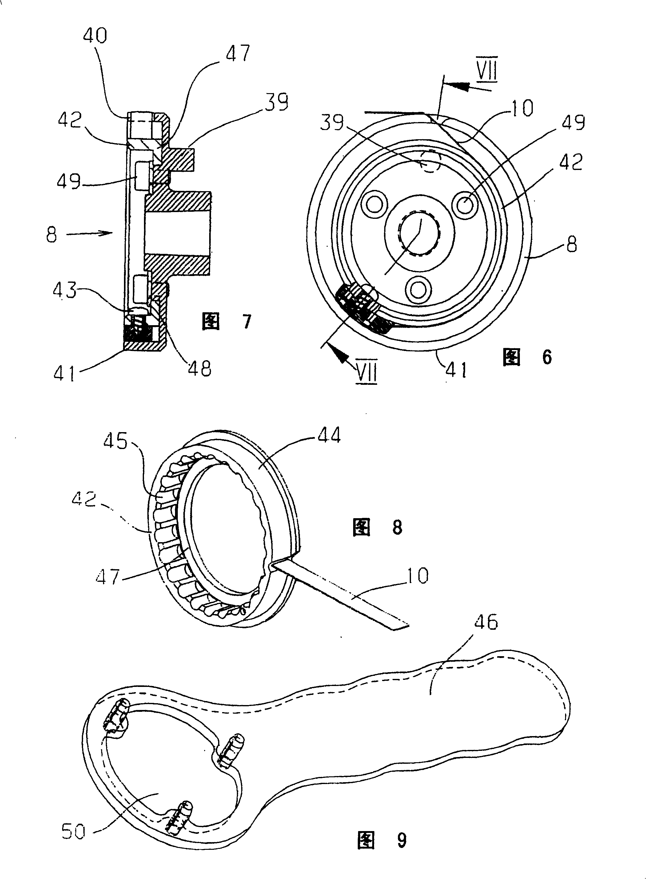
[0036]The transmission 4 has an electric motor 6 which drives the drum 8 via a reduction gear 7 . The electric motor 6 also has a sensor 9 which determines the angular position of the electric motor 6 . The motor 6 may be in the form of a servomotor, ie it has a permanent magnet excited rotor and a rotating field winding. It can also be called a permanent magnet excitation type...


PUM


Abstract

A warp knitting machine is equipped with at least one pattern guide bar (1) having the yarn guides (2), wherein the yarn guides are each connected to a motion control unit by an extension element (3). Further, the machine is so structured that the motion control unit has a driving device (4) at only one of ends of the pattern guide bar (1), the driving device has a drum (8), one of ends of the extension element (3) is fasten to the drum, and a return device (5) is positioned at only the other end of the pattern guide bar (1).

Description

technical field [0001] The invention relates to a warp knitting machine having at least one patterned bar with thread guides which are connected via tensioning elements to a movement control device. Background technique [0002] DE19938871C1 discloses this warp knitting machine. The known flower combs have a drive at each end. These two transmissions apply tension in opposite directions to the flower bar. Mass reduction is possible due to the use of tensile elements instead of the previously used rod-shaped combs. Like this, just can improve the working speed of warp knitting machine. However, it is difficult to achieve a sufficiently precise control of the yarn guide at higher operating speeds. Contents of the invention [0003] The object of the invention is to increase the precision when controlling the thread guide. [0004] In warp knitting machines of the type mentioned at the outset, this task is accomplished in that the motion control device has only a transmi...

Claims


Application Information

Patent Timeline
Patent Type & Authority Patents(China)
IPC IPC(8): D04B27/26D04B27/02D04B27/24D04B23/00
CPCD04B27/26D04B23/00D04B27/24
Inventor K·米斯塔
Owner KARL MAYER CHINA
Learn More