Electrical hair cutting appliance

An electric shaver, razor technology, applied in the direction of metal processing, etc., to achieve the effect of easy observation

Active Publication Date: 2009-04-15
BRAUN AG
View PDF10 Cites 5 Cited by
  • Summary
  • Abstract
  • Description
  • Claims
  • Application Information

AI Technical Summary

Problems solved by technology

[0004] Both known razors require a non-trivial effort from the user for the swiveling of the shaving heads

Method used


Image

  • Electrical hair cutting appliance
  • Electrical hair cutting appliance
  • Electrical hair cutting appliance

Examples


Embodiment Construction

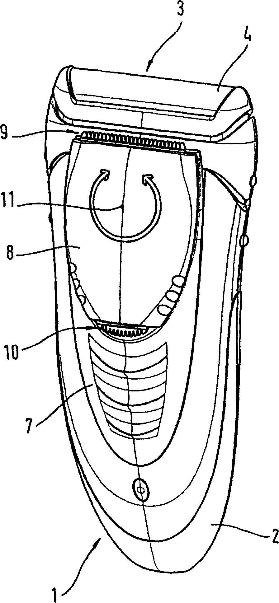
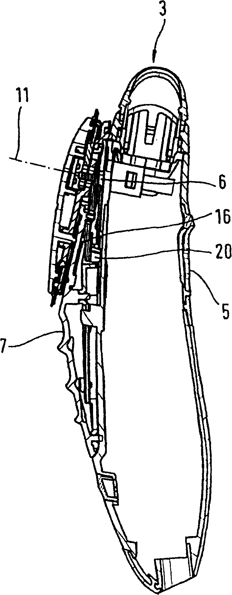
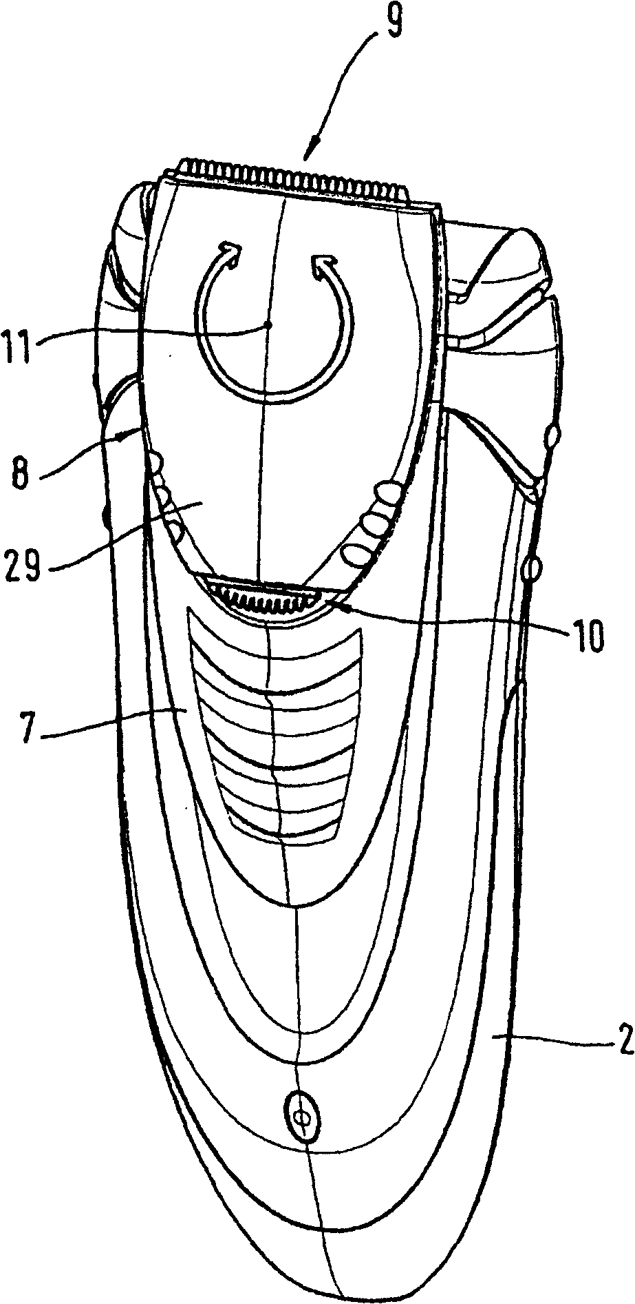
[0024] figure 1 shows a dry shaver 1 known per se with a housing 2 and a short-beard shaving system 3 . The short-beard shaving system consists of an upper blade 4 designed as a shaving foil, beneath which a lower blade (not shown in the drawing) moves reciprocally in an oscillating manner. The housing accommodates the drive motor required for this and, if necessary, a rechargeable battery and / or power supply and charging components for powering the drive motor. On the back of the case 2, an on / off switch 5 is provided. The power supply of the drive motor is turned on through the switch, and the drive motor not only oscillates to drive the lower blade of the short-beard shaving system 3 (not shown), but also continuously drives the drive member 6 protruding from the housing 2 . The drive element 6 is driven to oscillate parallel to the transverse axis of the dry shaver in the same way as the lower blade.

[0025] A slide switch 7 is arranged on the front of the casing 2, a ...


PUM


Abstract

The invention relates to an electrical hair cutting appliance comprising a housing (2) and a carrier body for at least one cutting system (9, 10), said carrier body (8) being pivotably mounted on the housing (2) about a rotational axis (11). The cutting system consists of at least two blade elements (30, 31, 36, 37) that can be moved in relation to each other by means of a drive motor, and the carrier body (8) is mounted, on one side, on an outer side of the housing (2).

Description

technical field [0001] The invention relates to an electric shaver. Background technique [0002] Such a shaver is known, for example, from WO 00 / 37225, according to which the shaver head can be pivotally mounted on the shaver housing, wherein two razor blades are assigned to a shaving comb, and then Each of them can be connected to the drive part of the drive device depending on the swivel position of the shaver head. The respective other shaving blades are then disconnected, so that only one shaving unit is always driven. The axis around which the razor head revolves runs parallel to the shaving edge of the shaving comb or razor blade. Both sides of the shaving head are supported in the housing of the razor by fork-shaped receivers. The axes of rotation are distributed in the center of the two shaving elements. Although the energy input of the drive unit connected to the shaving unit has an inclined extension to facilitate the introduction of the eccentric in any worki...

Claims


Application Information

Patent Timeline
Patent Type & Authority Patents(China)
IPC IPC(8): B26B19/06B26B19/10
CPCB26B19/10B26B19/105B26B19/063
Inventor 马蒂亚斯·韦策尔诺贝特·克罗伊茨丹尼尔·迪策尔福尔克尔·施滕格马蒂亚斯·马特恩
Owner BRAUN AG
Why Eureka
Try Eureka