
Relay with protection cover

A technology of protective cover and relay, applied in relay ventilation/cooling/heating, relay base/casing/cover, etc., can solve the problem of shallow depth of glue filling hole 113, affecting the smoothness and efficiency of the manufacturing process, and inconvenient to observe the filling degree, etc. question

Inactive Publication Date: 2009-04-08
EXCEL CELL ELECTRONICS
View PDF2 Cites 0 Cited by
  • Summary
  • Abstract
  • Description
  • Claims
  • Application Information

AI Technical Summary

Problems solved by technology

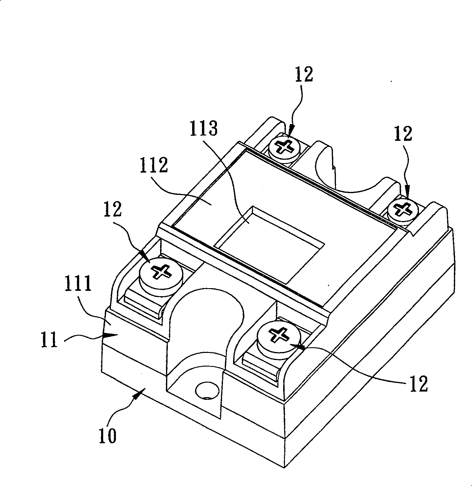
[0008] 1. Since the housing 11 is fixedly connected to the surface of the bottom plate 10 (such as locking), and then connected by filling and sealing glue, in terms of structure, the two do not actually have direct joints with each other, Close and stable structure, so under long-term use, there will be gaps between the casing 11 and the bottom plate 10, so that moisture is easy to invade, and the casing 11 is easy to shake, which affects the firmness and safety of installation and use.
[0009] 2. In the process of filling and sealing, because the operator observes the filling state through the glue filling hole 113, but the depth of the glue filling hole 113 is very shallow, so it is inconvenient to observe the filling degree, thus causing the operation tendency Slowly, there may even be cases where the sealant overflows due to carelessness, affecting the smoothness and efficiency of the entire manufacturing process
[0010] 3. In addition, the more important thing is that during use, since the wiring part 12 is in an exposed state, once the power is turned on and someone accidentally touches the wiring part 12, it is easy to get an electric shock and cannot provide Safer protection function in use

Method used


Image

  • Relay with protection cover
  • Relay with protection cover
  • Relay with protection cover

Examples


Embodiment Construction

[0025] The present invention will be described in detail below in conjunction with the accompanying drawings and embodiments.

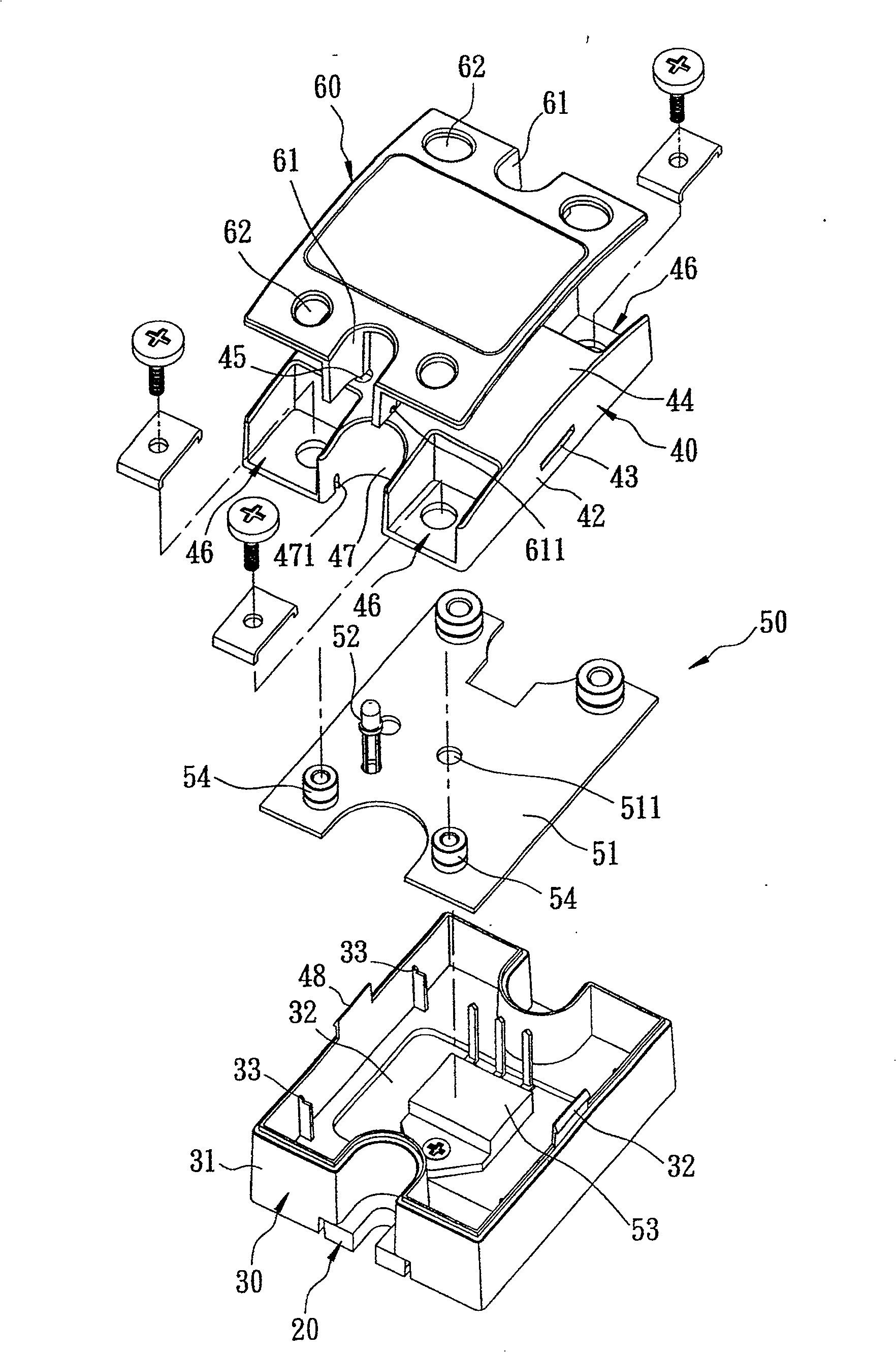
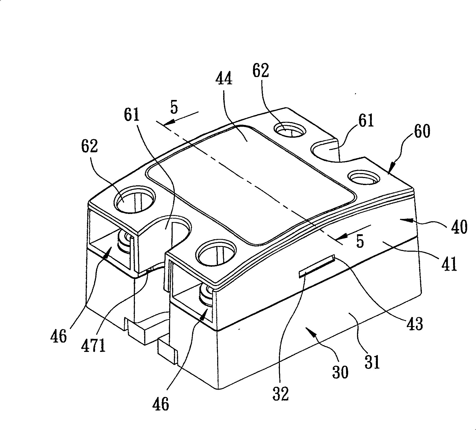
[0026] Such as figure 2 , 3 , 4, a preferred embodiment of the relay with a protective cover of the present invention includes a base plate 20, a housing 30, a shell 40, a control unit 50, and a protective cover 60.

[0027] Such as figure 2 , 3 , 5, the bottom plate 20 is a cooling plate and includes a bottom wall 21 and a connecting wall 22 .

[0028] The bottom wall 21 has a first plate surface 211 , a second plate surface 212 opposite to the first plate surface 211 , and a surrounding surface 213 connected to the first and second plate surfaces 211 , 212 .

[0029] The connecting wall 22 protrudes from the surrounding surface 213 and has a concave portion 221 extending to the surrounding surface 213 and being concave relative to the second plate surface 212 .

[0030] The casing 30 is directly embedded in the peripheral edge of the bottom p...


PUM


Abstract

A relay with protective cover consists of base plate, shell, shell jacket, control unit set in shell and protective cover pin-jointed on shell jacket. It is featured as arranging multiple wire connection unit being projected on shell jacket at control unit and enabling to pin-turn said protective cover to cover or to expose said wire connection units for protecting personnel from accident of electric shock.

Description

technical field [0001] The invention relates to a relay, in particular to a relay with a protective cover. Background technique [0002] Such as figure 1 As shown, a conventional relay includes a base plate 10 , a housing 11 disposed on the base plate 10 , and four wiring portions 12 disposed on the housing 11 . [0003] The bottom plate 10 is a heat sink. [0004] The casing 11 includes a surrounding wall 111 connected to the bottom plate 10, a top wall 112 connected to the periphery of the surrounding wall 111, and a glue hole 113 arranged on the top wall 112. The casing 11 is provided with a The control unit (not shown in the figure) provides the function of power switching. [0005] The wiring part 12 is respectively arranged in the four corners of the housing 11, and extends to the interior of the housing 11 to electrically connect the control unit. The wiring part 12 can provide the connection of multiple wires to form a switch that can switch the power of each wire...

Claims


Application Information

Patent Timeline
Patent Type & Authority Patents(China)
IPC IPC(8): H01H45/02H01H45/12
Inventor 李希哲
Owner EXCEL CELL ELECTRONICS
Learn More