Method and apparatus for realizing automatic control of milling and plaing work and work speed for milling and planing machine

A technology of working speed and milling machine, applied in the control field of milling, can solve the problems of sudden increase in the working torque of the milling drum, damage to the components of the working device, incompatibility, etc., so as to improve the construction efficiency, improve the quality, and prevent the boring car. Effect

Inactive Publication Date: 2009-03-18
厦工(三明)重型机器有限公司
View PDF8 Cites 0 Cited by
  • Summary
  • Abstract
  • Description
  • Claims
  • Application Information

AI Technical Summary

Problems solved by technology

However, it still has the following disadvantages: when hard objects such as large stones or steel pipes are encountered during the milling process, the working torque of the milling drum will increase suddenly. , the milling drum is prone to damage to the working device components (such as cutters); if the travel speed of the milling machine is manually reduced and the gear ratio of the transmission is reduced to reduce the working speed of the milling drum based on the operator's experience, road milling will inevitably occur. The problem of poor flatness and poor construction efficiency is not suitable for construction on various complex road surfaces

Method used


Image

  • Method and apparatus for realizing automatic control of milling and plaing work and work speed for milling and planing machine
  • Method and apparatus for realizing automatic control of milling and plaing work and work speed for milling and planing machine

Examples


Embodiment Construction

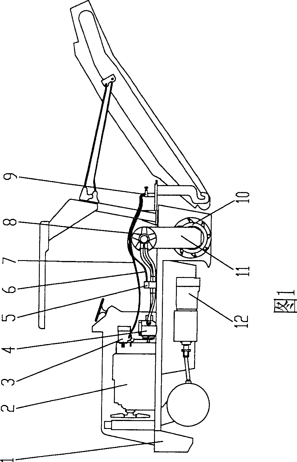
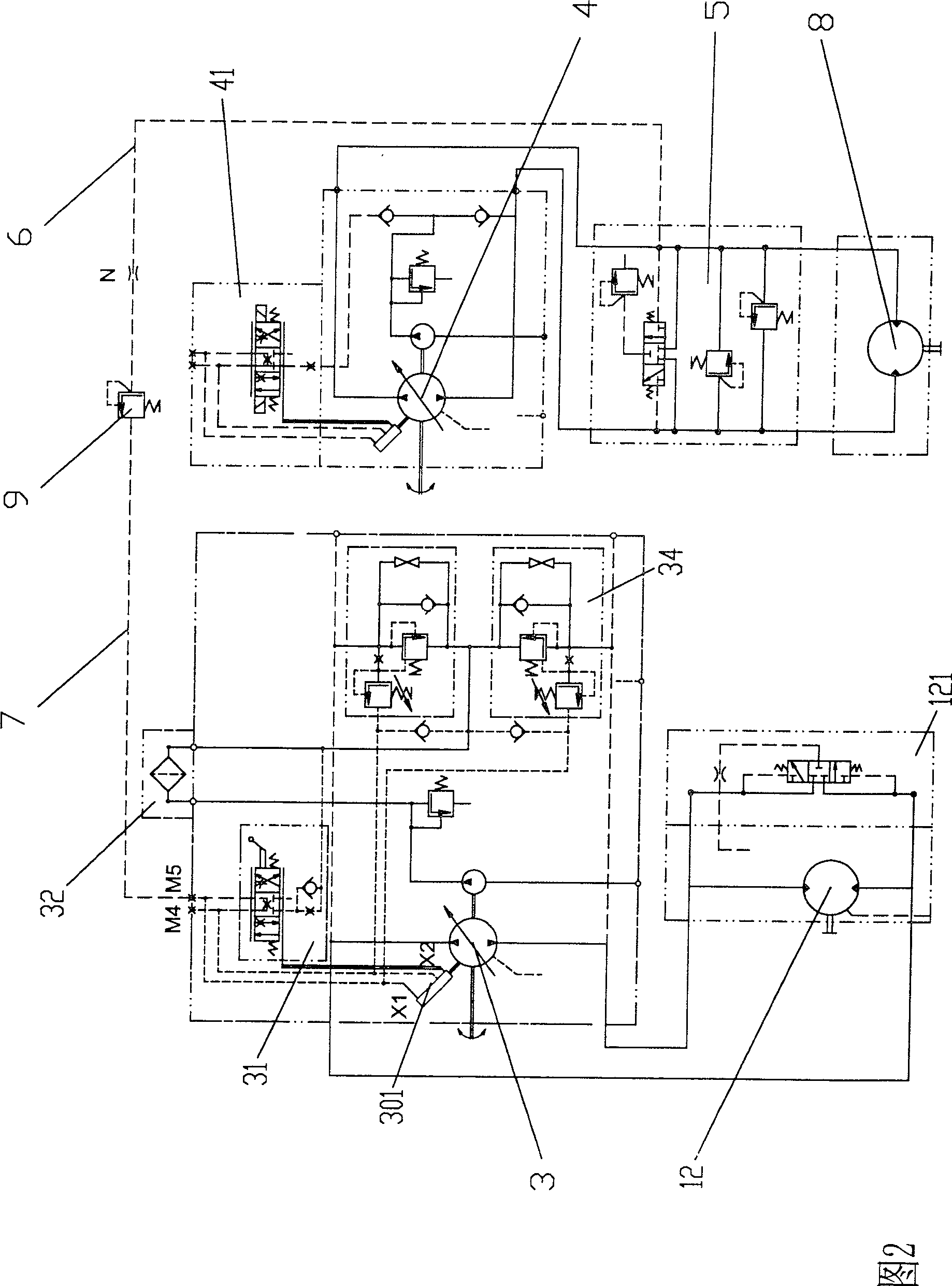
[0015] The structure of an embodiment of the device for realizing the milling work of the milling machine and the automatic control of the working speed of the present invention is shown in FIG. 1 . Engine 2, driving pump with servo valve 3, working pump with servo valve 4, high pressure valve of working pump 5, low pressure pipeline 6, high pressure pipeline 7, working hydraulic motor 8 are installed on the frame 1 of the device , overflow valve 9 and sprocket wheel case 11, the milling drum 10 of driving hydraulic motor 12 and band milling cutter head is installed on the bottom of frame 1. The travel hydraulic motor 12 drives the wheels. The main shaft of the engine 2 drives the main shaft of the driving pump 3 and the main shaft of the working pump 4 through the transmission parts respectively. The working hydraulic motor 8 is installed above the sprocket box 11, and the power is transmitted to the milling drum 10 through a chain transmission.

[0016] Please refer to Fig...


PUM


Abstract

The present invention relates to a method for implementing automatic control of milling-planing work and milling-planing speed of milling-planing machine and its equipment. It is characterized by that its equipment includes a running hydraulic system of said milling-planing machine, said running hydraulic system is composed of running pump, running pump servo-valve and running hydraulic motor, said running hydraulic system is driven by an engine. Said equipment also includes a working hydraulic system composed of working pump, working pump servo-valve and working hydraulic motor, said working hydraulic system can be used for driving milling-planing drum to mill, plane and finish pavement.

Description

technical field [0001] The invention relates to a milling control method for a hydraulically driven road surface milling machine in road construction, and the equipment working according to the method. technical background [0002] At present, the frame of the domestically produced hydraulically driven road milling machine is equipped with an engine, a travel drive pump, a travel drive pump servo valve, a working engine, a transmission and a sprocket box, and a travel drive motor and a belt milling machine are installed under the frame. Milling drum for planer heads. The engine drives the travel drive pump to rotate, and the travel drive pump servo valve controls the flow direction and flow of hydraulic oil delivered by the travel drive pump to the travel motor, thereby controlling the direction and speed of the milling machine. At present, the working transmission devices of domestically produced milling machines are roughly divided into two schemes: one is mechanical tran...

Claims


Application Information

Patent Timeline
Patent Type & Authority Patents(China)
IPC IPC(8): E01C23/06
Inventor 张应林徐远钦
Owner 厦工(三明)重型机器有限公司
Why Eureka
Try Eureka